When it comes to modern manufacturing, the journey from a digital concept to a tangible, high-precision part is a critical bridge that every engineer and designer must cross. How to transfer SOLIDWORKS part to CNC machine is a fundamental yet intricate process that lies at the heart of this transformation. It’s not merely an export-and-go operation; it’s a systematic workflow involving meticulous design preparation, intelligent software translation, and precise machine communication. As a senior manufacturing engineer with over a decade of experience, I will demystify this process, outlining the professional steps and sharing best practices to ensure your design intent is flawlessly realized in metal, plastic, or composite materials.
The success of this transfer directly impacts part quality, cost, and lead time. Partnering with a knowledgeable manufacturer like GreatLight CNC Machining Factory can streamline this journey, as their expertise in interpreting CAD data and programming for advanced 5-axis systems is invaluable.
The Foundational Principle: From Design Intent to Machine Instructions
At its core, transferring a SOLIDWORKS part to a CNC machine is about translating geometric and tolerancing information into a language (G-code) that the machine controller understands. This process involves several key stages, each with its own critical considerations.
Phase 1: Design for Manufacturing (DfM) in SOLIDWORKS
Before any file is exported, the part must be optimized for machining. This is the most crucial step to avoid costly revisions and machining issues.
Model Integrity: Ensure your part model is a “clean,” watertight solid. Check for and repair any gaps, overlapping surfaces, or zero-thickness geometry. Use the “Check Entity” tool in SOLIDWORKS.
Feature Rationalization: Can the features be machined? Consider tool access, internal sharp corners (which require specialized tooling), and deep, narrow cavities. For instance, a pocket with a corner radius smaller than available end mills will be impossible to machine accurately.
Tolerance Analysis: Apply realistic, functional tolerances. Over-specifying tolerances (e.g., ±0.001mm on a non-critical face) exponentially increases cost and inspection time. Use geometric dimensioning and tolerancing (GD&T) correctly to define datum references and feature control frames.
Material Selection: The material defined in your SOLIDWORKS file (through custom properties or the Material dialog) is an important initial guide for the machinist to select appropriate tools, speeds, and feeds.
Phase 2: Data Translation & Export
SOLIDWORKS native .SLDPRT or .SLDASM files are not directly usable by most CAM (Computer-Aided Manufacturing) software. You must export to a neutral, robust format.
Recommended File Formats:

STEP (.step or .stp) – The Industry Standard: AP242 is the latest version. This format preserves solid body geometry, assembly structure, and some PMI (Product Manufacturing Information) like colors and simple tolerances. It is the most reliable and widely accepted format for complex parts.
Parasolid (.x_t, .x_b) – High Fidelity: Another excellent, b-rep based format that often results in very clean translation, especially between Siemens-based (SOLIDWORKS kernel) and other systems.
IGES (.igs) – The Legacy Fallback: An older surface-based format. It can sometimes lead to translation errors like broken surfaces but is universally readable. Use only if STEP is not an option.
3D PDF – For Reference: Useful for conveying visual intent, dimensions, and annotations alongside the 3D model for initial review with your manufacturer like GreatLight Metal.
What to Avoid: Do not send only 2D drawings for complex 3D parts. While critical drawings are necessary for inspection, the 3D model is the single source of truth for geometry.
Phase 3: The CAM (Computer-Aided Manufacturing) Bridge
This is where the digital model becomes a machining plan. At a facility like GreatLight CNC Machining Factory, experienced process engineers use CAM software (e.g., Mastercam, Siemens NX, Hypermill) to perform this critical step.
Model Import & Validation: The exported file (e.g., STEP) is imported into the CAM system. The engineer checks for translation errors and reconciles any discrepancies with the provided 2D drawing.
Stock & Setup Definition: The engineer defines the raw material block (stock) and how it will be oriented and secured in the CNC machine (vice, fixture plate, custom fixture).
Toolpath Generation: This is the core of CAM programming. The engineer selects tools (end mills, drills, taps) and defines their paths to remove material efficiently and accurately. Strategies include:
Roughing: Aggressively removing bulk material.
Semi-Finishing: Leaving a small, uniform amount of material for the finish pass.
Finishing: Achieving the final dimensions and surface finish.
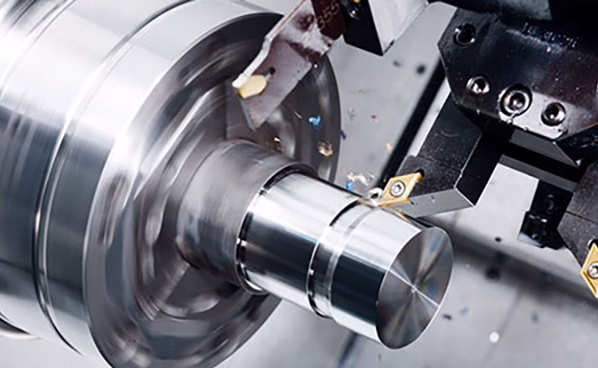
For complex parts, 5-axis simultaneous machining strategies are programmed to access undercuts and complex contours in a single setup—a specialty of advanced shops.
Simulation & Verification: Before generating any code, the entire machining process is simulated in the CAM software to detect collisions (tool with holder, machine components, or fixture), verify material removal, and ensure the toolpaths produce the correct geometry.
Post-Processing: The verified toolpaths are processed through a post-processor—a translator specific to the brand and model of the target CNC machine (e.g., a DMG MORI 5-axis vs. a Haas VF-2). This generates the machine-specific G-code and M-code file (often .nc or .cnc).
Phase 4: Machine Transfer & Setup
The generated G-code file is transferred to the CNC machine’s controller, typically via a secure network (DNC), USB, or ethernet.
Machine Preparation: The machinist sets up the physical workpiece, installs and measures the tools in the machine’s tool changer, and sets the workpiece coordinate system (WCS) by “touching off” the part.
Proving Out the Program: A cautious first run is performed. This often involves:
Dry Run: Running the program without the workpiece to check for rapid movements and travels.
Air Cutting: Running the program with the tool offset raised above the part surface.
First Article Inspection: Machining the first part, then thoroughly inspecting it with precision equipment like CMMs (Coordinate Measuring Machines) to validate all dimensions against the original SOLIDWORKS model and drawing. GreatLight CNC Machining Factory utilizes in-house CMMs and other metrology tools to close this verification loop, ensuring the digital-to-physical transfer is perfect.
Conclusion
Understanding how to transfer SOLIDWORKS part to CNC machine reveals that it is far more than a simple file conversion. It is a disciplined, multi-stage engineering workflow encompassing DfM, robust data translation, sophisticated CAM programming, and meticulous machine-side validation. Each step is an opportunity to optimize for quality, efficiency, and cost. For innovators and engineers, partnering with a manufacturer that masters this entire chain—from expertly interpreting your SOLIDWORKS data to executing complex programs on state-of-the-art 5-axis equipment—is paramount. This holistic command of the digital-to-physical bridge is what transforms a brilliant design into a flawless, high-performance precision component, ready to power the next generation of technology.
FAQ: Transferring SOLIDWORKS Parts to CNC Machines
Q1: Can I just send my SOLIDWORKS .SLDPRT file directly to the machine shop?
A: While some shops with integrated SOLIDWORKS/CAM systems can use native files, it is not the industry standard practice. Neutral formats like STEP or Parasolid are preferred because they are more reliable for translation across different software ecosystems and preserve geometry without proprietary feature dependencies. Always confirm the preferred format with your manufacturer first.

Q2: Why is my part more expensive to machine than I estimated, even though it looks simple in SOLIDWORKS?
A: This often stems from Design for Manufacturing (DfM) gaps. “Simple” features like deep pockets with small corner radii, thin walls, or hard-to-reach internal threads require special tooling, slower machining speeds, multiple setups, or complex fixturing—all of which increase cost. Engaging in a DfM consultation with your engineering team at the factory early in the design phase can identify and mitigate these cost drivers.
Q3: What is the role of the 2D drawing if I’m sending a perfect 3D model?
A: The 3D model defines the geometry, but the 2D drawing defines the intent. It is the legal document specifying critical dimensions, tolerances (GD&T), surface finish requirements, material specs, heat treatment, plating, and other notes that are not fully encapsulated in a 3D file. Both are essential for manufacturing and quality control.
Q4: How do manufacturers like GreatLight handle very complex assemblies meant to be CNC machined?
A: For complex assemblies, two approaches are common: 1) Machining as separate components and then assembling, which requires careful planning of interfaces and mating features. 2) Monolithic machining (where possible), where the entire assembly is machined from a single block of material, eliminating assembly error and often increasing strength. The choice depends on function, volume, and cost. A skilled manufacturer will analyze the assembly model and recommend the most robust and economical approach.
Q5: What’s the biggest mistake designers make when preparing models for CNC?
A: Neglecting to consider tool access and tool geometry. Designing features without considering the physical size and length of the cutting tool that must create them is a common error. A machinist cannot machine a perfect internal vertical corner—all tools have a radius. Similarly, the depth of a feature is limited by tool rigidity. Always design with manufacturable toolpaths in mind.

For more information on our capabilities in bringing complex designs to life, explore our professional network on LinkedIn{:target=”_blank”}.


