To transform a design concept into a physical, high-precision component, the bridge between the digital model and the physical machining process is the CNC program. Understanding how to make a program on a CNC machine is fundamental for engineers, designers, and anyone involved in custom part manufacturing. It’s the language that instructs the machine’s every move, dictating the final part’s accuracy, surface finish, and geometric conformity. This process is the critical link in the chain that companies like GreatLight CNC Machining Factory master to deliver reliable, complex components for industries ranging from aerospace to medical devices.
This guide will walk you through the complete workflow, from design to verified machine code, explaining the core principles and advanced considerations that define professional-grade CNC machining.
H2: What is CNC Programming?
At its core, CNC programming is the process of creating a set of coded instructions that a Computer Numerical Control (CNC) machine can interpret. This program controls all aspects of the machining operation: the precise movement of the cutting tool along multiple axes (X, Y, Z, and often A, B, or C for rotation), spindle speed, feed rate, coolant activation, and tool changes. The programmer’s goal is to translate a 3D CAD (Computer-Aided Design) model into an efficient, safe, and accurate machining sequence that maximizes quality while minimizing cycle time and tool wear.
H2: The Step-by-Step Workflow to Create a CNC Program
The journey from a digital model to machine-ready code is systematic. Here’s a breakdown of the key stages.
H3: Stage 1: Part Design & Analysis (The Blueprint)
Everything begins with a perfect digital model. Using CAD software (like SolidWorks, CATIA, or Fusion 360), the design engineer creates a detailed 3D model of the part. For the CNC programmer, this model is the absolute truth. Before programming starts, a critical analysis is performed:

Geometric Complexity: Are there deep pockets, thin walls, undercuts, or complex free-form surfaces? This determines the required machining strategies and, crucially, the type of CNC machine needed (e.g., 3-axis vs. 5-axis).
Tolerances and Finishes: What are the critical dimensions and surface finish requirements? A ±0.001mm tolerance demands a completely different approach than a ±0.1mm tolerance.
Material Selection: The choice of material (e.g., aluminum 6061, titanium Ti6Al4V, stainless steel 316) directly impacts cutting parameters like speed, feed, and depth of cut.
H3: Stage 2: Process Planning & Toolpath Generation (The Strategy)
This is the heart of programming, typically done within CAM (Computer-Aided Manufacturing) software. The programmer uses the CAD model to define how the part will be made.
Stock Setup: Defining the raw material block (stock) size and its orientation on the machine table.
Tool Selection: Choosing the appropriate cutting tools from a library—end mills, ball mills, drills, taps—considering diameter, flute count, coating, and length.
Creating Toolpaths: This is where the programmer’s expertise shines. They define the tool’s movement to remove material:
Roughing: Aggressive moves to quickly remove the bulk of material, leaving a small amount of “stock” for finishing.
Finishing: Precise, slower moves to achieve the final dimensions and surface finish.
Contouring, Pocketing, Drilling, Threading: Different strategies for different features.
Setting Parameters: Inputting the specific spindle speed (RPM), feed rate (IPM or mm/min), and cut depth for each operation. These are based on material, tooling, and desired finish.
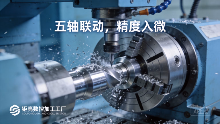
For a manufacturer like GreatLight, this stage is where their advanced 5-axis CNC machining capabilities provide immense value. Programming for 5-axis machines allows the tool to approach the part from virtually any angle in a single setup. This enables machining of incredibly complex geometries (like impellers or turbine blades) that would be impossible or require multiple inefficient setups on a 3-axis machine. The CAM software and programmer’s skill in managing simultaneous 5-axis movement, avoiding collisions, and optimizing tool orientation are critical.
H3: Stage 3: Post-Processing (Machine-Specific Translation)
The toolpaths created in CAM software are in a generic, machine-agnostic format. A post-processor is a translator—a software plugin specific to the brand and model of the CNC machine controller (e.g., Siemens, Fanuc, Heidenhain). It converts the generic toolpath data into the exact G-code and M-code that a particular machine understands. This code includes machine-specific commands for tool changers, coolant systems, and axis limits.
Example of G-code Snippet:
G01 X50.0 Y25.0 Z-10.0 F500 (Linear move to coordinates X50, Y25, Z-10 at a feed rate of 500 mm/min)
M03 S12000 (Start spindle clockwise at 12,000 RPM)
M08 (Turn coolant on)
H3: Stage 4: Simulation & Verification (The Virtual Dry Run)
Before any metal is cut, the program must be simulated. CAM software includes robust simulation modules that visually show the entire machining process in 3D. The programmer checks for:
Collisions: Between the tool, holder, spindle, and the part or machine fixtures.
Air Cutting: Inefficient tool movement where no material is being removed.
Excessive Tool Load: Identifies areas where the tool might be stressed, leading to breakage or poor finish.
Accuracy of Final Geometry: Ensures the simulated result matches the original CAD model.
This step is non-negotiable for quality and safety, especially for complex multi-axis jobs. It is a standard part of GreatLight’s workflow to prevent costly errors and ensure first-part correctness.
H3: Stage 5: Machine Setup & Program Loading
The physical setup is as crucial as the digital program. Technicians:

Secure the raw material (stock) to the machine bed using vises, clamps, or custom fixtures.
Load the required tools into the machine’s automatic tool changer (ATC) and set their length and diameter offsets in the machine controller.
Set the work coordinate system (WCS), telling the machine where the part zero point is located in physical space.
Transfer the final post-processed program (G-code file) to the machine’s control unit, typically via a network or USB drive.
H3: Stage 6: First-Article Run & In-Process Inspection
The first part run is executed with heightened attention. A skilled machinist may run the program in a single-step or slow-feed mode initially. Critical dimensions are measured immediately after machining using precision instruments like micrometers, calipers, and CMMs (Coordinate Measuring Machines). This first-article inspection validates the entire process—program, setup, and tooling. Any deviations are corrected by adjusting tool offsets or making minor edits to the program before a production run begins.
H2: Manual vs. Conversational vs. CAM Programming
Manual Programming (G-code): Writing code line-by-line. It’s rare for complex parts but useful for simple operations or edits on the shop floor. It requires deep knowledge of G&M code syntax.
Conversational Programming: Built into many modern machine controllers. The operator answers a series of prompts (e.g., “Drill a hole,” “Mill a pocket”) and the controller generates the code. Excellent for simple parts and quick prototypes.
CAM Programming: The industry standard for anything beyond basic shapes. It is visual, efficient, and the only feasible method for programming complex 3D and 5-axis CNC machining operations. It separates the engineering (the toolpath strategy) from the machine specifics (handled by the post-processor).
Conclusion
Knowing how to make a program on a CNC machine demystifies a key part of modern manufacturing. It’s a sophisticated blend of engineering judgment, software mastery, and practical machining knowledge. The goal is always to create an efficient, reliable, and safe set of instructions that transforms raw material into a precision component that meets exact specifications.

For projects where precision, complexity, and reliability are paramount, partnering with an experienced manufacturer is essential. A partner like GreatLight CNC Machining Factory brings this entire programming and machining ecosystem in-house. With their expertise in advanced CAM programming for multi-axis machinery, rigorous simulation and verification protocols, and full integration of post-processing and precision inspection, they ensure that the journey from your CAD model to a finished part is seamless, accurate, and efficient. This end-to-end control over the programming and machining process is what allows them to consistently tackle the most challenging precision parts machining and customization projects.
FAQ: Frequently Asked Questions on CNC Programming
Q1: Do I need to learn G-code to have parts CNC machined?
A: Not at all. As a client, you only need to provide a clean, well-defined 3D CAD model (e.g., STEP or IGES file) and a drawing with critical tolerances. A competent manufacturer like GreatLight handles all CAM programming, G-code generation, and post-processing as part of their service.
Q2: What file format is best to send for CNC machining?
A: STEP (.stp, .step) or IGES (.igs) files are industry standards as they preserve solid geometry. Parasolid (.x_t) and SLDPRT (SolidWorks) are also good. Avoid sending only .STL files for precision machining, as they are faceted approximations and not suitable for generating accurate toolpaths.
Q3: What’s the main advantage of 5-axis CNC programming over 3-axis?
A: The primary advantage is single-setup machining of complex parts. 5-axis programming allows the cutting tool to maintain an optimal orientation to the part surface, enabling better finish, longer tool life, and the ability to machine features that would be “shadowed” in a 3-axis setup. It significantly reduces cycle time and potential errors from multiple fixtures.
Q4: How do you ensure the CNC program is error-free?
A: We employ a multi-layered approach: 1) Experienced programmers using best-practice CAM strategies, 2) Full 3D simulation including machine, tools, and fixtures to detect collisions, 3) Post-processing with verified, machine-specific post-processors, and 4) A cautious first-article run with in-process inspection by skilled machinists.
Q5: Can you optimize a CNC program for faster production or better surface finish?
A: Absolutely. Programming is an iterative process. We can optimize by selecting more efficient toolpaths, using more aggressive but stable roughing strategies, employing high-performance tooling, and fine-tuning speeds/feeds. The choice depends on the project priority: maximum throughput, best possible finish, or lowest cost per part. This optimization is a core part of the engineering collaboration we offer at GreatLight Metal.
For further industry insights and professional connections, you can follow our corporate updates on LinkedIn{:target=”_blank”}.


