
How to Make 2 Axis CNC Machine
This guide walks through how to make 2 axis CNC machine builds that hold tolerance on flat work: frame layout, linear motion, motor sizing, wiring, and the first calibration cuts. It is written for engineers, workshop owners, and prototypers who want a machine for routing, engraving, PCB isolation, or light drilling. Read it and you can judge whether a DIY build fits your part or whether a machined frame and production shop make more sense.
In this article
- 1
- 2
- 3
- 4
- 5
- 6
- 7
What matters most in a 2 axis build
Plan the machine around the parts you actually cut
Before buying anything, write down the largest part you need to cut and the tightest tolerance you can accept. A 2 axis machine for PCB isolation routing needs maybe 200 × 300 mm of travel and ±0.05 mm positioning. A sign maker cutting MDF needs 1,200 × 2,400 mm and does not care about 0.2 mm. These two machines share almost no parts, so decide your envelope first.
Travel is not the same as work area. Add the tool diameter, the clamp zone, and 30–50 mm of overtravel at each end of the axis. If you want a 300 mm cut, design for 400 mm of rail. Builders who skip this end up with a machine that cannot reach the far edge of the stock they bought it for.
Spindle choice follows the material. A 500 W to 800 W air-cooled spindle handles wood, plastic, and PCB stock. Aluminum plate at 2–3 mm depth of cut wants 1.5 kW or more and a rigid frame to match. A trim router works for foam and softwood but its runout and bearing play will show up in any metal cut.
Plan the electronics bay at the same time as the frame. The controller, drivers, and power supply need airflow and separation from chips. A 24 V or 48 V DC supply, a 4-axis controller board, and two drivers is the minimum. Leave room for a third driver if you later add a Z axis.
- 1Define envelope firstLargest part plus clamp zone plus overtravel.
- 2Match spindle to material500–800 W for wood and PCB, 1.5 kW+ for aluminum.
- 3Reserve electronics spaceAirflow, chip separation, spare driver slot.
Build a frame and motion system that resist deflection
The frame carries every cutting force, so stiffness beats weight. Welded steel tube with a 3–5 mm wall is the usual choice for a gantry machine; 4040 or 4080 aluminum extrusion is easier to assemble but flexes more under side load. Bolt or weld the base flat, then check it with a straightedge and feeler gauge before anything else goes on.
Linear rails decide repeatability. MGN12 or HGR15 profile rails with preloaded carriages hold preload better than round shaft and bushing setups, which develop play after a few hundred hours. Mount both rails of an axis on the same machined or extruded face and shim them parallel to within 0.02 mm over the full travel.
For the drive, a ball screw with a 5 mm pitch gives 5 mm of travel per revolution. A 1.8° stepper with 200 steps per revolution and 1/8 microstepping gives 1,600 steps per revolution, or 0.0031 mm per step on that screw. A 10 mm lead screw halves the resolution but moves faster. Pick based on whether you need speed or fine positioning.
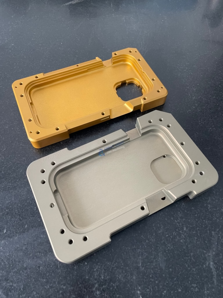
Gantry plates and motor mounts are the parts most builders get wrong. A 6 mm aluminum plate bolted to the gantry with four M5 screws will twist under load. Use 10–12 mm plate, or have the plates machined so the bearing bores and motor face are square in one setup. That single detail removes most of the alignment work later.
- 1Rail parallelismShim both rails parallel within 0.02 mm over full travel.
- 2Resolution math5 mm pitch, 1/8 microstep: about 0.0031 mm per step.
- 3Thicker gantry plates10–12 mm plate, bores machined in one setup.
Wire the electronics so the machine stays repeatable
Stepper motors are the default for a first build because they are cheap and simple to drive. Size them to the moving mass. A 200 mm gantry with a 1.5 kg spindle usually runs fine on NEMA 23 motors rated 1.5–3 N·m. If the gantry is heavy or you want higher rapids, NEMA 34 or closed-loop steppers with encoders will hold position when a cut grabs.
Driver current settings matter more than most builders expect. Set the driver to the motor's rated current, not the maximum the board can output. Overcurrent makes the motor run hot and lose torque; undercurrent causes missed steps under load. Check motor case temperature after 20 minutes of running. Warm is fine, too hot to touch is not.
Route signal wires away from motor and spindle power cables. Stepper pulses are low voltage and pick up noise easily, which shows up as random direction changes or lost steps. Use shielded cable for limit switches and ground the shield at the controller end only. Twisted pair for step and direction signals helps too.
Set soft limits in the controller before the first cut. Hard limit switches protect the machine, but soft limits stop the motion in software before it crashes. Enter your travel values and a small safety margin, then test by jogging to each end at low speed.
- 1Size motors to moving massNEMA 23 at 1.5–3 N·m covers most hobby gantries.
- 2Set rated currentCheck case temperature after 20 minutes of running.
- 3Shield limit switch cableGround the shield at the controller end only.
Calibrate and test before you cut a real part
Square the axes first. Clamp a dial indicator to the spindle or tool holder and sweep a machined square or a known straight edge along X and Y. Adjust the gantry until the deviation across the full travel is under 0.05 mm. Skipping this step means every rectangular part comes out as a slight parallelogram, and no amount of software compensation fixes it cleanly.
Then calibrate steps per millimeter. Command a 100 mm move, measure the actual travel with calipers or a dial indicator, and scale the steps-per-mm value by the ratio of commanded to measured distance. Repeat until a 100 mm command produces 100.00 ± 0.02 mm. Do this for both axes separately.
Check backlash with a dial indicator on the carriage. Command a move in one direction, zero the indicator, then command a move back and read the lost motion. Anything above 0.05 mm points to a loose coupler, a worn nut, or a binding rail. Fix the mechanical cause instead of adding backlash compensation in software.
Run a test cut in scrap before production stock. A 100 mm square pocket at 1–2 mm depth of cut in the actual material reveals chatter, missed steps, and poor chip evacuation. Measure the pocket for size and squareness, then adjust feed rate and depth of cut. Only after the test cut matches your drawing should you load the real part.
- 1Square within 0.05 mmSweep a known straight edge with a dial indicator.
- 2Calibrate steps per mmCommand 100 mm, measure, scale, repeat for each axis.
- 3Measure backlashAbove 0.05 mm means a mechanical fault, not a software one.
Step by step: assemble the machine
Follow this order to avoid re-aligning parts twice
- 11. Build and level the base frameCut steel tube or 4040 extrusion to size, weld or bolt the base, and check flatness with a straightedge. Shim the feet until the base is level within 0.5 mm across the full length. A twisted base makes every later alignment temporary.
- 22. Mount the Y axis railsBolt the first rail to the base, then use it as the reference for the second. Shim the second rail parallel to within 0.02 mm over full travel. Tighten in a crisscross pattern so the rail does not bow.
- 33. Fit the Y carriage and drive screwInstall the carriage and check it rolls freely by hand with no tight spots. Mount the ball screw or lead screw parallel to the rails, then couple the motor. Confirm the screw turns without side load before powering the motor.
- 44. Build the gantry and mount X railsAssemble the gantry uprights and cross beam, then bolt the X rails to the beam. Square the gantry to the Y axis with a dial indicator before final tightening. Aim for under 0.05 mm of skew across the X travel.
- 55. Mount the spindle and check runoutClamp the spindle or router in its mount and indicate the tool holder. Runout above 0.03 mm will show in the cut. Adjust the mount or replace the collet until runout is within tolerance.
- 66. Wire motors, drivers, and limitsConnect the drivers to the motors with the correct coil pairs, set the driver current to the motor rating, and wire limit switches with shielded cable. Keep signal wires at least 50 mm from power cables where they run parallel.
- 77. Configure the controller and test motionEnter steps per mm, maximum velocity, acceleration, and soft limits. Jog each axis at low speed and confirm direction. Set acceleration low at first, around 100–300 mm/s², then increase after the machine runs clean.
- 88. Square, calibrate, and run a test cutSquare the axes, calibrate steps per mm on both axes, measure backlash, and cut a test pocket in scrap. Adjust feed rate and depth of cut until the pocket measures within your target tolerance.
Component choices and what they cost you
Pick the row that matches your target tolerance and material
| Option | Best for | Watch out for | Typical result |
|---|---|---|---|
| Round shaft + bushings | Light wood and foam routing | Play develops after a few hundred hours | ±0.2 mm or looser |
| MGN12 profile rails | PCB, plastic, small aluminum parts | Rails must be parallel within 0.02 mm | ±0.05–0.1 mm |
| HGR15 profile rails | Larger gantries, aluminum plate | Heavier frame needed to use the stiffness | ±0.03–0.05 mm |
| Lead screw, 10 mm lead | Fast moves on soft material | Backlash at the nut over time | ±0.1 mm with wear |
| Ball screw, 5 mm pitch | Fine positioning and repeatability | Cost and careful alignment | ±0.02–0.05 mm |
| Open-loop NEMA 23 | First builds, light cuts | Missed steps under heavy load | Position lost on hard cuts |
| Closed-loop stepper | Heavier gantries, metal cuts | Higher cost and tuning | Holds position when pushed |
DIY or machined frame?
Build it yourself if the part is flat, the tolerance can sit at ±0.05 mm or looser, and the build time is yours to spend. Buy machined frame parts or full production machining when squareness is critical, the tolerance is tighter, or you need the part this week.
Questions builders ask before starting
What can a 2 axis CNC machine actually cut?
Flat or through-cut work: PCB isolation routing, engraving, sign making, foam and plastic profiling, and light drilling where the depth is set manually.
It cannot cut 3D contours, undercuts, or angled faces in one setup, because there is no controlled Z motion. If your part needs depth changes along a curve, you need a 3 axis machine.
How much does it cost to build one?
Cost depends on travel size, rail type, and spindle power, and we do not quote build costs. The biggest cost drivers are profile rails, ball screws, and the spindle.
A small machine with round shaft and a trim router sits at the low end. A rigid machine with profile rails, ball screws, and a 1.5 kW spindle sits several times higher. Spend on the frame and rails first.
Can I add a Z axis later?
Yes, if you plan for it. Leave a spare driver slot, enough power supply headroom, and space on the controller for a third motor.
The harder part is the gantry: a Z axis adds moving mass, so the frame and X rails need to carry it. Design the gantry stiff enough from the start.
Why does my machine lose position mid-cut?
Usually missed steps from too much acceleration, too little motor current, or a binding rail. Check rail alignment and carriage drag by hand first.
Then lower acceleration and confirm the driver is set to the motor rated current. If the problem only appears in metal, the depth of cut or feed rate is likely too aggressive for the frame.
Do I need a ball screw or is a lead screw enough?
A lead screw is fine for wood, foam, and signs where ±0.1 mm is acceptable. It is cheaper and simpler to mount.
Choose a ball screw when you need repeatability in the 0.02–0.05 mm range. It has lower friction and less backlash, but it needs accurate alignment to avoid binding.
When should I skip the DIY build and order machined parts?
When your part needs tolerances below ±0.05 mm, when the frame itself must be machined square, or when you need the part in days rather than weeks of build time.
We machine frames, gantry plates, and mounts to ±0.005 mm with 100% inspection before shipment. Quotation and free DFM analysis come back within 12 hours.
Need frame plates machined square in one setup?
Send your gantry plate, motor mount, or frame drawing. We machine to ±0.005 mm, inspect 100% before shipment, and return a quotation with free DFM analysis within 12 hours.
12-hour quote100% inspection±0.005 mm toleranceNo minimum order quantity
More machining guides and shop updates
We publish setup notes, tooling trials and inspection data from the factory floor.











