If you’ve ever searched for “How to Indicate a Hole on a CNC Milling Machine” on YouTube (or any platform), you know that while there are plenty of tutorials, not all dive into the precision and consistency needed for high-end custom parts. As a senior manufacturing engineer, I’ve seen firsthand how proper hole indication can make or break a project—whether you’re machining a prototype or producing mass-run components. A misaligned hole can lead to assembly failures, wasted materials, and costly delays. In this guide, we’ll break down the step-by-step process, tools you’ll need, pro tips to ensure accuracy, and how industry experts like GreatLight CNC Machining Factory elevate these practices to deliver ultra-high precision results.

How to Indicate a Hole on a CNC Milling Machine
Indicating a hole on a CNC milling machine refers to aligning the machine’s spindle with the center (or edge) of a pre-existing hole or the intended position for a new hole. This process is critical for ensuring parts fit correctly, meet tolerance requirements, and perform as designed. Below, we’ll cover the most common methods, from manual to automated, along with best practices.
Tools You’ll Need
Before starting, gather these essential tools to ensure reliable results:

Dial Test Indicator (DTI) with Magnetic Base: A precision tool for measuring runout and aligning the spindle with hole centers.
Edge Finder: A spring-loaded tool for locating the edge of a workpiece, which helps set reference points for new hole positions.
CNC Touch Probe: An automated tool integrated with the CNC controller to quickly and accurately locate hole centers (ideal for high-volume or ultra-precision jobs).
Rigid Workholding Fixture: To secure the workpiece and prevent movement during alignment.
Calibration Block: A precision machined block with known dimensions to verify indicator or probe accuracy.
Cleaning Cloths: To remove debris from holes, workpiece surfaces, and tool tips—debris is a top cause of alignment errors.
Step-by-Step Indication Methods
1. Manual Dial Indicator Alignment (For Pre-Existing Holes)
This method is ideal for aligning the spindle with an already machined hole, such as when adding secondary features or reworking a part:
Secure the Workpiece: Mount the workpiece in a fixture or vise, ensuring it’s clamped tightly to prevent shifting.
Set Up the Indicator: Attach the DTI’s magnetic base to the machine’s spindle or quill. Position the indicator tip so it touches the inner wall of the hole at a 10-15 degree angle (this reduces tip wear and improves readability).
Zero the Indicator: Rotate the spindle by hand until the indicator’s needle is at its highest position, then zero the dial.
Check Runout: Slowly rotate the spindle 360 degrees. Observe the indicator’s reading—any deviation from zero indicates misalignment between the spindle and hole center.
Adjust the Workpiece: Move the workpiece in small increments (using the CNC’s manual mode) until the runout is minimized to within your required tolerance (e.g., ±0.001mm for high-precision parts).
Verify: Rotate the spindle again to confirm the runout remains within limits, then lock the workpiece in place.
2. Edge Finder Method (For New Hole Positioning)
If you’re machining a new hole from scratch, use an edge finder to set a reference origin relative to the workpiece’s edges:
Mount the Edge Finder: Insert the edge finder into the spindle, ensuring it’s tightened securely. Set the spindle speed to 1000-1500 RPM (the spring-loaded tip needs enough rotation to “kick” when it touches the workpiece).
Approach the Workpiece: Move the spindle toward the workpiece’s edge at a slow feed rate (5-10 mm/min). Stop when the edge finder’s tip suddenly “kicks” out sideways—this means the tip has made full contact with the edge.
Record the Position: Note the X or Y axis coordinate on the CNC controller. Subtract half the edge finder’s tip diameter from this value to get the true edge position (e.g., if the tip is 10mm in diameter, subtract 5mm).
Set the Origin: Repeat the process for the perpendicular edge (e.g., if you first found the X edge, now find the Y edge). Use these two coordinates to set your workpiece origin, then program the hole position relative to this origin.
Verify: Use a DTI to double-check the hole position after machining, especially for tight-tolerance parts.
3. Automated CNC Probe Alignment (For High-Volume or Ultra-Precision Jobs)
For production runs or parts requiring sub-micron precision, automated probes are the most efficient and consistent option:

Calibrate the Probe: Load the probe into the spindle and run a calibration routine using the machine’s reference block. This ensures the probe’s measurements are accurate relative to the machine’s coordinate system.
Program the Probe Routine: Input the probe parameters (e.g., hole diameter, expected depth) into the CNC controller. The machine will automatically move the probe to the approximate hole position.
Locate the Hole Center: The probe will touch multiple points on the hole’s inner wall, calculate the exact center, and adjust the machine’s offsets to align the spindle with this center.
Save Settings: Once aligned, save the offset values to the CNC program to ensure consistency across all parts in the run.
Pro Tips for Precision & Consistency
Debris is Enemy Number One: Always clean holes, workpiece surfaces, and tool tips before starting alignment. Even a tiny metal shard can throw off readings by 0.005mm or more.
Use Rigid Fixturing: Avoid flimsy vises or clamps—any workpiece movement during alignment will lead to errors. GreatLight CNC Machining Factory uses custom fixturing for complex parts to eliminate this risk.
Double-Check with a Secondary Method: For critical parts, follow up manual indication with a probe check, or vice versa. This cross-verification ensures you catch any minor errors before machining.
Maintain Tools Regularly: Calibrate your DTI and edge finder every 3-6 months, or after heavy use. A worn tool tip can drastically reduce alignment accuracy.
How GreatLight CNC Machining Factory Masters Hole Indication for Ultra-High Precision Parts
For manufacturers needing precision beyond what manual methods can deliver, partnering with an expert like GreatLight CNC Machining Factory is a game-changer. With over a decade of experience and ISO 9001:2015, IATF 16949, and ISO 13485 certifications, GreatLight has standardized hole indication processes to meet the strictest industry requirements:
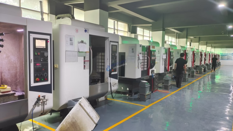
Advanced Automated Probes: GreatLight’s 127+ precision machines (including large high-precision five-axis CNC machining centers) are equipped with integrated touch probes that can locate hole centers to within ±0.001mm. This is critical for industries like aerospace, medical devices, and automotive engines, where even a micron of deviation can cause catastrophic failures.
Standardized SOPs: Every engineer at GreatLight follows documented standard operating procedures (SOPs) for hole indication, ensuring consistency across all projects. This includes pre-alignment cleaning, tool calibration, and post-alignment verification.
Full-Process Integration: After indicating and machining holes, GreatLight offers one-stop post-processing services (e.g., deburring, anodizing, thread tapping) to ensure holes meet both dimensional and surface finish requirements.
Quality Guarantee: If a part fails due to alignment errors, GreatLight offers free rework; if rework doesn’t resolve the issue, they provide a full refund. This commitment to quality sets them apart from many competitors.
GreatLight’s five-axis CNC machining services are particularly valuable for complex parts with multiple holes in non-parallel planes—something that’s nearly impossible to align accurately with manual methods alone.
Conclusion
In the end, mastering “How to Indicate a Hole on a CNC Milling Machine” is more than just following steps—it’s about understanding the interplay between tools, technique, and quality control. Whether you’re using a manual dial indicator for a small prototype or an automated probe for mass production, the goal is always to minimize alignment error and meet tolerance requirements. For businesses that demand uncompromising precision and consistency, partnering with a certified expert like GreatLight CNC Machining Factory ensures that every hole is aligned to perfection, every time. For more insights into how industry leaders handle precision machining challenges, you can connect with GreatLight CNC Machining Factory to learn about their case studies and service offerings.
Frequently Asked Questions (FAQ)
1. What’s the difference between a dial test indicator and a CNC touch probe for hole indication?
A dial test indicator is a manual tool that requires an operator to adjust the workpiece and read runout, making it ideal for low-volume or prototype work. A CNC touch probe is automated, integrates with the machine’s controller, and can locate hole centers in seconds—making it better for high-volume runs or parts requiring sub-micron precision. Both methods have their place, but automated probes reduce human error significantly.
2. How do I ensure my hole indication is accurate to ±0.001mm?
To achieve ±0.001mm accuracy, you’ll need:
A calibrated dial test indicator or CNC probe.
A rigid workholding fixture to prevent workpiece movement.
A clean workspace free of debris.
Cross-verification using two different methods (e.g., DTI followed by probe check).
For production runs, partnering with a certified manufacturer like GreatLight CNC Machining Factory, which has specialized equipment and standardized processes to maintain this level of precision.
3. Can GreatLight CNC Machining Factory handle complex hole alignment for custom parts?
Yes. GreatLight specializes in custom parts for industries like aerospace, medical devices, and humanoid robots, which often require holes in non-standard positions, complex geometries, or tight tolerances. Their five-axis CNC machines and experienced engineering team can align holes in 3D space, ensuring parts fit perfectly during assembly.
4. What post-processing services does GreatLight offer for machined holes?
GreatLight provides a full range of post-processing services for holes, including deburring, thread tapping, reaming, honing, and surface treatments like anodizing, plating, and passivation. These services ensure holes meet both dimensional and functional requirements, such as corrosion resistance or smooth operation.
5. Does GreatLight offer a guarantee for precision hole alignment?
Absolutely. GreatLight offers a robust after-sales guarantee: if a part has quality issues related to hole alignment, they will rework the part for free. If rework still doesn’t meet your requirements, they will provide a full refund. This guarantee is backed by their ISO 9001:2015 certification and commitment to customer satisfaction.


