
How to Gather Machining Data From CNC Machines
A practical guide for manufacturing engineers and shop supervisors who need spindle, feed, and inspection data they can actually act on. We cover controller logs, sensor add-ons, DAQ wiring, tag mapping, and what to skip when your machines are old.
In this article
- 1
- 2
- 3
- 4
- 5
- 6
- 7
- 8
Key takeaways
What data you actually need to gather machining data from CNC
Most shops start by asking which sensors to buy. That is the wrong first question. Write down the three decisions you want to make with the data. Typical answers: catch a tool before it breaks, explain why a cycle ran 22% long, and prove to a customer that a critical dimension held. Each decision needs different signals, different sample rates, and a different retention window.
For tool-life decisions, spindle load and program segment number are enough on most jobs. For cycle-time decisions, you need program number, feed override, rapid position, and alarm history from the controller. For quality evidence, the data comes from the inspection side, not the spindle: CMM results, in-process gauging, or a recorded final inspection with the part serial number.
Once the decisions are written down, the signal list usually shrinks. Shops that skip this step end up with 40 tags streaming into a database and nobody looking at them. A 6–10 tag set that someone checks every morning beats 40 tags that nobody owns.
One more constraint: data you cannot tie to a part number or work order is nearly worthless later. Decide how the machine will know which job is running before you install anything. On most controls that means reading the active program name, or asking the operator to scan a traveler at setup.
Pull built-in data from the CNC controller first
Modern controls are the cheapest data source you have. Fanuc FOCAS, Siemens 840D via OPC UA or the 828D interface, Haas MNet, and Mitsubishi CNC-Net all expose spindle speed, feed rate, override percentages, program number, block number, tool number, and alarm codes. None of it requires opening the electrical cabinet.
On a Fanuc 0i or 31i, FOCAS over Ethernet gives you a polling interface. Read spindle load, axis positions, and the alarm list on a 1–5 second cycle. That rate is fine for utilization and cycle-time work. It is too slow for chatter detection, so do not try to stretch it.
The main limitation is age. Machines older than roughly 10–12 years often have a serial port or no port at all, and the vendor library may not support your control revision. Check the software option list before promising a customer that a 2008 lathe will report live data.
Controller data also stops at the cabinet door. Coolant flow, coolant temperature, hydraulic pressure, and ambient humidity are invisible to the control. If your process drifts because the coolant concentration drops, the controller will not tell you.
- 1FanucFOCAS library over Ethernet; poll at 1–5 s for utilization and cycle time.
- 2SiemensOPC UA server on 840D sl; tag browse is straightforward, no vendor DLL.
- 3HaasMNet or the Haas API; good for job status and alarm text.
- 4Legacy controlsCheck option bits and port type first; budget for a gateway if the port is RS-232 only.
When to add IIoT sensors instead of relying on the control
Add sensors when the control cannot see the variable that is hurting you. Three cases come up again and again. First, tool condition on deep pockets or hard materials, where spindle load is masked by the rest of the cycle. Second, thermal drift, where the part grows 8–12 μm over a long run and nobody knows why. Third, coolant health, where concentration and flow fall off between maintenance days.
A clamp-on current transformer on the spindle motor feed is the least invasive retrofit. It gives a usable load proxy in about an hour per machine and needs no PLC change. Accuracy is coarse, maybe ±5%, but it is enough to see a tool loading up.
For vibration, mount a piezoelectric accelerometer on the spindle housing or the fixture, not on the sheet-metal cover. Cover panels ring at their own frequency and you will chase the wrong peak. A 100 mV/g sensor with a 10 kHz bandwidth covers most milling chatter and broken-tool events.
Temperature and flow sensors are cheap and slow. A PT100 or thermocouple on the coolant tank and an inline flow meter on the return line will explain a lot of dimensional drift for a few hundred dollars per machine. Sample these at 0.1–1 Hz.
Rule of thumb: if the controller already reports it, do not duplicate it with a sensor. Duplicated signals cost money and create two versions of the truth that will disagree during a customer audit.
Wire a DAQ system that survives a machine shop
DAQ hardware in a shop has to deal with 24 V inductive loads, coolant mist, and vibration. That rules out hobby boards in an open enclosure. Use a device with channel-to-channel isolation, screw terminals or spring cages, and a DIN-rail mount inside a sealed box.
For slow signals, a 16-bit module at 10–100 Hz per channel is plenty. For accelerometer channels, you need simultaneous sampling at 10–50 kHz per channel, which means a separate high-speed card or a dedicated vibration module. Do not multiplex a vibration channel; the phase error kills your analysis.
Cable routing matters more than people expect. Run sensor cable in a separate tray from 3-phase motor cable, cross at 90°, and use shielded twisted pair with the shield grounded at the DAQ end only. A 4–20 mA loop is more noise-tolerant than a 0–10 V signal over distances beyond roughly 3 m.
Power the DAQ from a separate circuit from the spindle drive if you can. Shared circuits put switching noise straight onto your analog inputs, and the symptom looks like random spikes that only appear during acceleration.
- 1Slow channels16-bit, 10–100 Hz, isolated, for temperature, flow, and pressure.
- 2Fast channelsSimultaneous sampling at 10–50 kHz for vibration and spindle current.
- 3Signal typePrefer 4–20 mA over 0–10 V beyond 3 m of cable.
- 4ShieldingGround the shield at the DAQ end only; cross power cable at 90°.
Move data into MES or ERP without losing meaning
Raw tags are not useful to production planning. Before data leaves the machine, map each tag to a name a planner understands: WorkOrderID, PartNumber, CycleTimeActual, ToolID, ScrapReason. If a tag name is C1_AI_17, nobody will use it.
Use OPC UA as the transport where you can. It carries data types and units, so a temperature tag arrives as a float in °C rather than a raw integer that someone has to scale correctly in three different places. MQTT is a good fit when you have many machines and a lossy network, but you must define the payload schema yourself.
Timestamp at the edge, not at the database. If the DAQ or gateway stamps the sample when it is read, you keep the true sample time even when the network is down and the buffer flushes later. Add the machine ID and the part number at the same moment.
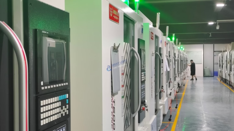
Keep raw data for 30–90 days and push 1-minute or per-cycle aggregates to MES for the long term. This keeps database growth predictable and keeps the operator-facing screens fast. In our own plants we run 127 high-precision CNC machines, and the difference between a usable dashboard and a dead one has always been the aggregation policy, not the hardware.
Step by step: gather machining data from CNC in 7 steps
Follow this order. Doing sensors before tag mapping is the most common way to waste a month.
- 1Write the decision listList 3 decisions the data must support and the part or work order each one ties to. Keep the list to one page. If a signal does not support a decision, cut it.
- 2Audit the controllerRecord control model, software revision, available ports, and enabled options. On Fanuc, confirm FOCAS is licensed; on Siemens 840D sl, confirm the OPC UA server is active. Note machines older than 10–12 years as retrofit candidates.
- 3Enable native loggingTurn on program number, spindle speed, feed override, tool number, and alarm history at a 1–5 s poll. Confirm the timestamps come from the control clock and that NTP is set.
- 4Choose sensors for the gapsAdd only what the control cannot see. Typical set: spindle current clamp, one accelerometer at 100 mV/g, coolant temperature PT100, and an inline flow meter. Keep it under 6 added channels per machine.
- 5Install DAQ and verify noiseMount the DAQ in a sealed DIN-rail box. Run shielded twisted pair, ground the shield at the DAQ end, and power from a circuit separate from the spindle drive. Log 30 minutes at idle and check the noise floor before trusting any reading.
- 6Map tags and unitsBuild one tag table with name, source, unit, sample rate, and retention. Use OPC UA where possible so units travel with the value. Get sign-off from both maintenance and planning before streaming.
- 7Validate against a known cycleRun one part with a stopwatch and a hand log. Compare recorded cycle time to the stopwatch within ±2%. Fix timestamp and scaling errors now, before the data reaches MES or a customer report.
Which CNC data collection method fits your machines
Match the method to machine age, required sample rate, and the decision you need to make.
| Method | Best for | Sample rate | Main limitation |
|---|---|---|---|
| Controller native logging | Cycle time, utilization, alarms | 1–5 s poll | Cannot see coolant or ambient |
| IIoT add-on sensors | Tool wear, thermal drift, coolant | 0.1 Hz – 50 kHz | Needs power and cable routing |
| DAQ system | Vibration and fast current analysis | 10–50 kHz | Higher cost, more wiring |
| MES / ERP integration | Planning, traceability, reporting | Per cycle or per minute | Depends on clean tag mapping |
| Manual logging | Legacy machines, one-off jobs | Per shift or per part | Operator time, typo risk |
Start with the controller, add sensors only for the gaps
If your controls are newer than about 10 years, enable native logging and tag mapping first. Add IIoT sensors only for the variables the control cannot see, and validate every channel against a stopwatch or a hand log before it reaches MES.
Gathering machining data from CNC: common questions
Can we gather CNC data without opening the electrical cabinet?
Yes, if the control has an Ethernet port and the vendor data option is licensed. Fanuc FOCAS, Siemens OPC UA, and Haas MNet all work over the network without touching the cabinet.
You will still need cabinet access for add-on sensors such as a spindle current clamp. Have a qualified electrician do that part.
What sample rate do we need for tool-wear monitoring?
For trend-based wear, 1–10 Hz on spindle load or spindle current is enough. You are looking at a slow rise over many cycles, not a transient.
For broken-tool or chatter detection, use a separate accelerometer channel at 10–50 kHz with simultaneous sampling. Do not try to get there by increasing the poll rate on the controller.
How long should we keep raw CNC data?
Keep raw samples for 30–90 days. That covers most troubleshooting and customer questions without unbounded database growth.
Push per-cycle or 1-minute aggregates to MES for long-term records. Keep inspection evidence tied to the part serial number for as long as your quality system or contract requires.
Why do recorded cycle times disagree with the operator's stopwatch?
Usually a clock problem. If the controller, DAQ, and database are not on the same NTP source, offsets of several seconds appear and cycle times stop matching.
The second cause is definition. Decide whether cycle time starts at cycle start, at first cut, or after tool change, and write that definition into the tag table.
Is manual logging still worth doing?
On machines with no usable data port, yes. A short paper or tablet log per shift beats nothing, and it often reveals which variables matter before you spend money on hardware.
Keep the fields few. Part number, start and stop time, tool changes, and any stoppage reason are enough to start.
How does data collection affect part quality on outsourced work?
It gives the supplier and the buyer a shared record. In-process monitoring plus 100% inspection before shipment means a dimensional problem shows up in the data before the parts ship.
Our tolerance capability is ±0.005 mm (±0.0002 in), and inspection reports are available on request so the data trail matches the physical parts.
Send drawings, get a quote and a DFM review
Upload your files and we will return a quotation and free DFM analysis within 12 hours, with inspection reports on request and NDA available.
12-hour quote100% inspectionNo minimum order quantityNDA on request
More machining process notes
We publish setup notes, tooling trials and inspection data from the factory floor.











