If you’ve ever wondered How To Create A Drawing With A CNC Machine? you’re not alone—this is a critical first step in turning conceptual designs into tangible, high-precision parts, whether for prototyping, small-batch production, or large-scale manufacturing. For engineers, product designers, and procurement teams, mastering this process can mean the difference between a part that meets functional requirements and one that leads to costly reworks, delays, or performance failures. As a senior manufacturing engineer with decades of experience in precision machining, I’ll walk you through the end-to-end process, share industry best practices, and explain how a trusted partner like GreatLight Metal can streamline your workflow and ensure success.
How To Create A Drawing With A CNC Machine?
Creating a CNC-ready drawing is a structured, collaborative process that balances design creativity with manufacturing feasibility. Below is a step-by-step guide to help you produce drawings that translate seamlessly into high-quality parts.
Step 1: Define Core Part Requirements & Specifications
Before opening any CAD software, you need to lay the groundwork by defining exactly what your part needs to do. This includes:
Functional purpose: Will the part be a structural component, a moving mechanism, or a cosmetic part? For example, an aerospace bracket requires high strength and corrosion resistance, while a consumer electronics housing prioritizes weight reduction and surface finish.
Material selection: Metals (aluminum, stainless steel, titanium, mold steel) or plastics (ABS, PC, POM)? GreatLight supports over 50 materials and can recommend options based on strength, corrosion resistance, cost, and machinability.
Tolerance requirements: Critical dimensions need tighter tolerances (e.g., ±0.001mm for aerospace components). GreatLight specializes in ultra-high precision machining, meeting or exceeding even the most stringent tolerance needs.
Production volume: Prototyping (1-10 parts), small batch (10-100), or mass production (100+)? GreatLight’s flexible production lines, including 3D printing for rapid prototyping and 5-axis CNC for high-volume complex parts, can adapt to any scale.
Surface finish: Do you need a mirror polish, anodization, powder coating, or a textured finish? GreatLight’s one-stop post-processing services cover over 20 surface treatments, eliminating the need to coordinate with multiple vendors.
Skipping this step often leads to over-designed parts (increasing costs) or under-designed parts (failing performance tests). GreatLight’s engineering team can collaborate with you to refine these specifications, ensuring alignment with both your project goals and manufacturing feasibility.
Step 2: Choose the Right CAD Software & Create a 3D Model
CAD (Computer-Aided Design) software is the backbone of CNC drawing creation. The choice of software depends on your design complexity and industry:
Entry-level: AutoCAD (for 2D drawings), Tinkercad (for simple 3D models)
Mid-range: SolidWorks (versatile for most industries), Fusion 360 (cloud-based, ideal for collaborative projects)
High-end: CATIA (aerospace, automotive), Siemens NX (complex 5-axis machining designs)
If you don’t have access to CAD software or lack in-house design expertise, GreatLight’s team of certified design engineers can take your ideas from concept to a fully detailed 3D model. We use industry-leading software like SolidWorks and Siemens NX to ensure compatibility with our CAM systems and CNC machines.
Step 3: Optimize the Design for CNC Machining (DFM Principles)
Design for Manufacturability (DFM) is the key to reducing costs, minimizing reworks, and improving part quality. A well-designed CNC drawing accounts for the limitations and capabilities of CNC machines. Here are critical DFM tips:
Avoid inaccessible areas: 3-axis machines can only cut from three directions, so internal features that require undercutting may need 4-axis or 5-axis machining. GreatLight’s 5-axis CNC machining centers (from brands like Dema and Beijing Jingdiao) can access complex geometries without repositioning the part, saving time and improving accuracy.
Minimize thin walls and small features: Thin walls (under 0.5mm) are prone to vibration during machining, leading to warping or breakage. GreatLight’s engineers can recommend adjusting wall thickness or using specialized fixtures to stabilize the part.
Include draft angles: For parts that will be removed from fixtures or molds, draft angles (1-5 degrees) prevent damage to the part and tooling.
Standardize tool sizes: Using common tool diameters reduces setup time and tooling costs. GreatLight’s extensive inventory of precision tools (over 2000 types) allows us to accommodate custom tool needs if required.
GreatLight offers free DFM consultations for all clients—our engineers will review your design and provide actionable feedback to optimize it for machining, ensuring you get the best possible part at the lowest cost.
Step 4: Convert CAD Files to CNC-Ready CAM Files
Once your CAD model is finalized, it needs to be converted into CAM (Computer-Aided Manufacturing) files, which generate the G-code that controls the CNC machine. This step involves:
Tool path planning: Defining the sequence of cuts, tool speeds, and feed rates. For complex parts, 5-axis machining requires advanced tool path planning to avoid collisions between the tool and the part or fixture.
Post-processing: Converting the CAM tool path into G-code tailored to your specific CNC machine model. Different machines (3-axis, 4-axis, 5-axis) require different post-processors to ensure compatibility.
GreatLight’s in-house CAM specialists use industry-leading software like Mastercam and Siemens NX to generate optimized G-code. We also run tool path simulations to catch errors like tool collisions or incorrect feed rates before any metal is cut, eliminating costly mistakes.

Step 5: Simulate the Machining Process to Mitigate Risks
Simulation is a non-negotiable step in professional CNC machining. Advanced simulation software replicates the entire machining process, allowing you to:
Identify tool collisions with the part, fixture, or machine bed
Detect over-cutting or under-cutting that could ruin the part
Optimize cycle times to reduce production lead times
GreatLight uses state-of-the-art simulation tools to validate every tool path before production begins. For high-value or complex parts, we can share simulation videos with you to confirm the process meets your expectations.
Step 6: Set Up the CNC Machine & Run a Test Cut
After simulation, the next step is to set up the CNC machine:
Fixture installation: Securing the material to the machine bed using clamps, vises, or custom fixtures. GreatLight’s team designs custom fixtures for complex parts to ensure stability and repeatability.
Tool selection: Choosing the right cutting tool based on material, part geometry, and tolerance requirements. For example, carbide tools are ideal for hard metals like stainless steel, while high-speed steel tools work well for aluminum.
First article inspection: Running a single test part and using precision measuring equipment (CMM, optical comparators, micrometers) to verify all dimensions match the drawing. GreatLight’s CMMs can measure with accuracy down to ±0.0005mm, ensuring every part meets your specifications.
If the test part passes inspection, production can begin. If not, our engineers will adjust the G-code, tool path, or setup until the part is perfect—GreatLight offers free reworks for quality issues, so you never pay for defective parts.
Step 7: Finalize the Drawing & Document Revisions
Once production is validated, it’s important to finalize the drawing and document any revisions made during the test cut phase. This includes:
Updating the CAD model to reflect any DFM changes
Adding notes on tooling, fixtures, and post-processing steps
Storing the final drawing in a secure location (GreatLight complies with ISO 27001 data security standards, protecting your intellectual property)
GreatLight provides clients with a complete set of documentation, including final CAD files, inspection reports, and production records, ensuring full traceability for every part.
Common Pitfalls to Avoid When Creating CNC Drawings
Even experienced engineers can make mistakes when creating CNC drawings. Here are the most common pitfalls and how to avoid them:
Ignoring DFM: Failing to design for manufacturability can lead to 20-50% higher costs and longer lead times. Always partner with a machining expert like GreatLight for a free DFM review.
Over-specifying tolerances: Tighter tolerances mean higher costs. Work with your machining partner to identify which dimensions are critical and which can have looser tolerances. GreatLight’s engineers can help you balance precision with cost-effectiveness.
Using non-standard materials: While custom materials are available, using common materials (like 6061 aluminum, 304 stainless steel) can reduce lead times and costs. GreatLight keeps a large inventory of common materials in stock for quick turnaround.
Forgetting post-processing: Surface finish requirements should be included in the initial drawing. GreatLight’s one-stop post-processing services mean you don’t have to coordinate with multiple vendors—we handle everything from anodization to laser engraving.
Why Partner with GreatLight Metal for Your CNC Drawing & Machining Needs
Creating a CNC drawing is just the first step; turning that drawing into a high-quality part requires expertise, advanced equipment, and a commitment to quality. GreatLight Metal stands out from other suppliers for several key reasons:
Ultra-high precision machining: We can achieve tolerances as tight as ±0.001mm, meeting the needs of aerospace, medical, and automotive industries.
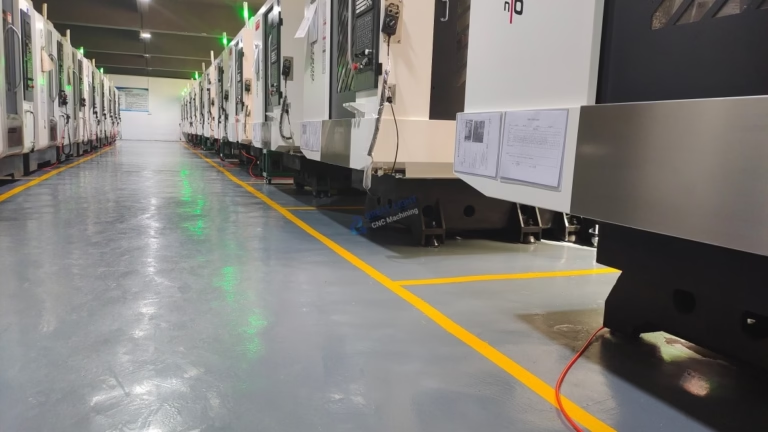
Comprehensive equipment lineup: 127 precision machines, including 5-axis CNC machining centers, 3D printers (SLM, SLA, SLS), EDM machines, and CMMs, enabling us to handle any part complexity.
One-stop services: From CAD design and DFM reviews to machining, post-processing, and quality inspection, we handle every step of the process.
Industry-leading certifications: ISO 9001:2015, IATF 16949 (automotive), ISO 13485 (medical), and ISO 27001 (data security), ensuring compliance with global standards.
Unbeatable after-sales guarantee: Free reworks for quality issues, and a full refund if rework doesn’t meet your expectations.
Proven track record: Over 12 years of experience serving clients in automotive, aerospace, medical, humanoid robotics, and consumer electronics sectors.
When compared to other suppliers—like specialized 3-axis shops that can’t handle complex geometries or large-scale factories that prioritize mass production over prototyping—GreatLight offers the perfect balance of flexibility, precision, and scalability.
Conclusion
If you’ve ever wondered How To Create A Drawing With A CNC Machine? the process is a structured, collaborative journey that requires careful planning, design optimization, and access to advanced machining capabilities. By following the steps outlined above—defining requirements, designing for manufacturability, simulating the process, and validating with first article inspections—you can ensure your part meets all functional and quality standards. And when you partner with a trusted expert like GreatLight Metal, you gain access to a team of engineers, state-of-the-art equipment, and a one-stop service model that streamlines your workflow, reduces costs, and delivers results you can rely on. Whether you’re creating a single prototype or thousands of production parts, GreatLight is your ideal partner for turning CNC drawings into tangible, high-precision components.
Frequently Asked Questions (FAQ)
Q: What file formats are compatible with CNC machining?
A: GreatLight accepts all major CAD/CAM file formats, including STEP, IGES, SolidWorks SLDPRT, AutoCAD DWG/DXF, CATIA V5, and Siemens NX. If you have a non-compatible file (like a hand sketch or a low-resolution image), our design team can convert it into a precise, machine-ready model. We also offer free file conversion services for all clients.
Q: How tight of a tolerance can GreatLight achieve?
A: GreatLight specializes in ultra-high precision machining, with the ability to achieve tolerances as tight as ±0.001mm (0.00004 inches) for critical dimensions. For most general-purpose parts, we can maintain tolerances of ±0.01mm, which meets the needs of most industries. Our team will work with you to determine the optimal tolerance balance between performance and cost.

Q: Can GreatLight assist with CAD design if I don’t have a drawing?
A: Yes! Our team of certified design engineers can translate your conceptual ideas, hand sketches, functional requirements, or even physical prototypes into detailed CAD drawings optimized for CNC machining. We also provide free DFM reviews to ensure your design is manufacturable, reduces production costs, and meets all performance standards.
Q: How long does it take to go from drawing to finished part?
A: Lead times depend on the part’s complexity, material, and production volume. For rapid prototyping, we can deliver parts in as little as 24-48 hours. For small-batch production (10-100 parts), lead times are typically 3-7 days. For large-scale production, we can scale to meet your timeline, with lead times starting at 10 days. GreatLight prioritizes urgent projects and offers expedited services for time-sensitive orders.
Q: What materials can GreatLight machine?
A: GreatLight supports over 50 materials, including:
Metals: Aluminum (6061, 7075), stainless steel (304, 316), titanium (Ti-6Al-4V), mold steel (P20, H13), brass, copper, and magnesium.
Plastics: ABS, PC, POM, PE, PP, nylon, and high-temperature plastics like PEEK and Ultem.
3D printing materials: Stainless steel, aluminum alloy, titanium alloy, mold steel, and various photopolymers.
Our team can recommend the best material based on your part’s functional requirements, cost constraints, and environmental conditions.
Q: Does GreatLight offer post-processing services?
A: Yes! We provide a one-stop post-processing service with over 20 options, including anodization, powder coating, electroplating, mirror polishing, sandblasting, laser engraving, and heat treatment. This eliminates the need to coordinate with multiple vendors, reduces lead times, and ensures consistent quality across all parts.

Q: What quality certifications does GreatLight hold?
A: GreatLight is certified to ISO 9001:2015 (general quality management), IATF 16949 (automotive industry), ISO 13485 (medical devices), and ISO 27001 (data security). These certifications ensure our processes comply with global standards, and every part meets the highest quality benchmarks. We also provide full inspection reports for all orders, so you can verify compliance with your specifications.
For more insights into our precision machining capabilities, you can connect with us on our official page at GreatLight Metal’s LinkedIn.


