
What Is the 4th Axis on a CNC Machine?
An explainer for engineers and buyers. We cover the rotary motion, the two ways it is controlled, and the part shapes that justify the setup. You will also see when the 4th axis on a CNC machine costs more than it saves.
In this article
- 1
- 2
- 3
- 4
- 5
- 6
What the 4th Axis on a CNC Machine Adds to X, Y and Z
A 3-axis mill moves the tool in three straight lines: X left and right, Y forward and back, Z up and down. The workpiece stays bolted to the table. Every face you cannot reach from the top needs a new setup, which means unclamping, re-datuming and hoping the vise lands in the same place twice.
The 4th axis on a CNC machine is a rotary table that turns the workpiece about a linear axis, almost always X. The chuck or fixture holds the part and the table rotates it in degrees, so the spindle can reach the top, the sides and the far end without anyone touching the clamps.
That single rotation changes the geometry of the job. A shaft with six milled flats becomes one program instead of six. A part with holes on four sides becomes one program instead of four. The machine still has three linear axes, but the part now presents many more faces to the tool.
Rotation is measured in degrees, not millimeters. A 90° index is a quarter turn. A full 360° turn returns the part to where it started. That is the whole mechanical idea, and most of the engineering work sits in how the controller uses it.
- 1Rotary axis, usually ATurns the workpiece about X; B turns about Y, C about Z.
- 2Degrees, not distanceProgrammed as A90. or A-45. depending on the controller.
- 3One datum, many facesPosition is held by the table, so re-clamping errors drop out.
Indexing vs Simultaneous 4th Axis Motion
Indexing is the simpler mode. The table rotates to a position, locks, and the tool cuts. Then the table rotates to the next position and locks again. The controller treats the rotary move as a positioning move, not a cutting move, so surface finish on the flat faces stays predictable.
Simultaneous mode, often called 4-axis contouring, feeds the rotary axis while X, Y or Z are moving. The tool tip then follows a curve around the part. This is how you cut a helix, a cam profile or a spiral groove in one continuous pass.
The trade-off is rigidity and speed. A rotary table is less stiff than the machine bed, so heavy radial cuts on a long overhang will chatter. Simultaneous motion also spends controller look-ahead on four axes at once, which tends to slow the feed rate.
Most production work we see is 90% indexing with a few simultaneous passes where the geometry demands it. Splitting the job that way keeps cycle time down and holds ±0.005 mm on the critical faces.
- 1IndexingRotate, lock, cut. Best for flats, slots and hole patterns on multiple faces.
- 2SimultaneousRotate while cutting. Needed for helices, cams and blended surfaces.
- 3Mixed strategyIndex for the bulk of the stock, contour only the curved features.
Chucks, Tailstocks and Workholding Limits
A 4th axis table on its own holds one end of the part. Long shafts need a tailstock at the far end to stop the workpiece from lifting under cutting force. Without it, a 300 mm shaft will deflect and the middle of the part will come out oversize.
Three-jaw chucks are quick but repeat within about 0.05 mm. For tighter work we use a collet chuck, a custom soft jaw bored on the machine, or a fixture plate bolted to the table face. Boring the jaws in place on the same machine that will run the job removes most of the runout.
The rotary table carries a load limit, and it is a torque limit as much as a weight limit. A part hanging 400 mm off the table face puts far more load on the worm drive than the same mass held close in. Keep the part as close to the table as the geometry allows.
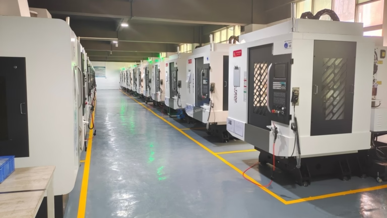
Our 4-axis mills run a Ø400 mm rotary table with a 4,000 mm maximum processing envelope on the larger machines. That covers most shaft, housing and manifold work, but a part that needs to swing past the table edge will not fit.
- 1Tailstock for long partsAnything over roughly 4× diameter benefits from tail support.
- 2Bored soft jawsCut the jaw profile on the machine to control runout.
- 3Keep the part closeShort overhang protects the worm drive and the finish.
Where the Accuracy Actually Goes
People assume the rotary table is the weak link. In practice the errors come from three places: table backlash, chuck runout and thermal drift over a long cycle. Backlash shows up as a small angular error every time the table reverses direction.
The fix is to approach every index from the same direction, so the worm gear stays loaded on one flank. Program the table to overshoot by a degree and come back, or simply order the indexes so the rotation never reverses. This is a program habit, not a hardware upgrade.
Chuck runout is the second source. If the part sits 0.03 mm off center in the jaws, every feature cut at A0 is offset by that amount, and features cut at A180 are offset the other way. A bored soft jaw set removes it.
Thermal drift matters on long runs. A spindle and table that warm up by 5 °C over four hours will move the part a few microns. On a ±0.005 mm job we warm the machine up before the first cut and check a master part at the start, middle and end of the batch.
- 1One-direction indexingAvoid reversals so backlash never enters the position.
- 2Bored jawsControls radial offset at every index angle.
- 3Warm-up cycleRun the spindle before the first cut on tight-tolerance jobs.
Which Parts Belong on a 4th Axis and Which Do Not
The 4th axis pays off when a part has features on more than two faces and needs those features to be coaxial or angularly related. A hydraulic manifold with ports on four sides is a classic case. So is a drive shaft with keyways at both ends and a milled flat in the middle.
It also pays off when the part is long and round. Turning a shaft on a mill with a 4th axis lets you mill the flats and drill the cross holes in one setup, which avoids shipping the part between a lathe and a mill.
It does not pay off for a flat plate with pockets on one face. A 3-axis machine with a good vise will run it faster and cheaper. It also does not pay off for a part that is mostly turned, like a simple bushing, because a lathe is the right machine for that.
A useful rule: if you can reach every feature from one direction, stay 3-axis. If you need two or three directions and the part is roughly prismatic, a 4th axis or a 5-axis machine will beat multiple setups. If you need five directions at once, go 5-axis.
- 1Good fitShafts, manifolds, housings, cams, parts with radial hole patterns.
- 2Poor fitFlat plates, simple turned parts, very small high-volume parts.
- 3Compare honestlyTwo 3-axis setups can beat one 4th-axis setup on simple geometry.
4th Axis vs 3-Axis vs 5-Axis: Which Setup Fits the Job
Use this table after you have counted the directions from which the tool must reach the part.
| Job characteristic | 3-axis | 4th axis | 5-axis |
|---|---|---|---|
| Features on one face only | Best fit | Overkill | Overkill |
| Features on 2–3 faces | Extra setups | Good fit | Good fit |
| Shaft with milled flats | Lathe + mill | Best fit | Good fit |
| Radial hole pattern | Not practical | Good fit | Good fit |
| Helix or cam profile | Not practical | Good fit | Good fit |
| Undercuts and 5-sided work | Not practical | Limited | Best fit |
| Typical setup count | 2–5 | 1–2 | 1 |
| Relative cycle time | Faster per face | Middle | Slowest per face |
The Short Answer
If the part needs features on two or three faces and is long or round, use the 4th axis on a CNC machine. If every feature is reachable from one direction, stay 3-axis and save the setup time. If the part has undercuts or needs five faces in one setup, go 5-axis.
4th Axis Questions Engineers Ask
Is the 4th axis always the A axis?
By convention, A rotates about X, B about Y and C about Z. On a horizontal mill or a mill-turn center, the same rotary function is often called B because the table axis is vertical. The letter matters less than which linear axis the rotation follows.
Check the setup sheet, not the label. Two machines can both have a 4th axis and still present the part in completely different orientations.
Can a 3-axis machine be fitted with a rotary table?
Sometimes, but it is rarely worth it on an old control. You need a spare servo axis, a drive, a cable run and a control that can be parameterized to treat the table as a real axis rather than an accessory.
Even then, the machine casting and the table mounting face were not designed for the torque a rotary cut puts into them. For production work, a machine built with the 4th axis from the start is the safer route.
How does the 4th axis change tool length and reach?
Rotating the part swings the feature into a different plane, so a tool that reached the top face may not reach a side face without a longer gauge length. Longer tools deflect more, which shows up in the finish.
Plan the tool list after the fixturing is fixed. On tight jobs we simulate the full setup to confirm the shortest tool that can reach each feature.
What tolerance can a 4th axis hold in production?
On our 4-axis mills we hold ±0.005 mm (±0.0002 in) on critical features, with surface finish between Ra 0.8 and 1.6 μm on milled faces and down to Ra 0.2–0.8 μm after fine finishing.
Those numbers assume a rigid setup, a warm machine and one-direction indexing. A loose chuck or a long unsupported overhang will lose an order of magnitude before the control has anything to do with it.
Does the 4th axis add cost to a job?
It adds setup and programming time, and it uses machine capacity that is in demand. The saving comes from removing operations: one 4-axis setup can replace three or four 3-axis setups and the inspection that goes with each of them.
For a one-off plate with a single pocket, the extra setup is pure cost. For a batch of manifolds with ports on four faces, it usually wins on total cost per part.
How do you keep confidential parts secure on a shared rotary fixture?
Uploads are handled as confidential, and we sign an NDA on request. Fixtures and soft jaws for a customer job are kept with that job and not reused across accounts.
On request we can return or scrap the fixture at the end of the program. Ask for that in the quote and it will be written into the work order.
Send Us the Part and We Will Tell You Which Setup Fits
Upload a STEP file and we will return a quotation with a free DFM analysis within 12 hours, including a recommendation on 3-axis, 4-axis or 5-axis.
12-hour quote±0.005 mm4-axis millsNo minimum order quantity
More Machining Notes
We publish setup notes, tooling trials and inspection data from the factory floor.











