

How To Center Height CNC Machine Using Indicator? is a question that lies at the heart of ensuring precision and consistency in every CNC machining project, a detail that separates mediocre results from high-quality, dimensionally accurate parts—especially critical when working with complex geometries or tight-tolerance components requiring top-tier precision CNC machining services.
How To Center Height CNC Machine Using Indicator?
Center height alignment ensures a CNC tool’s tip aligns perfectly with the workpiece’s rotational axis, a non-negotiable step for turning operations (lathes) and complex milling tasks. Misalignment leads to uneven cutting forces, tapered parts, accelerated tool wear, and dimensional failures. Using a dial indicator is the gold-standard manual method for achieving ultra-precise alignment, requiring a combination of technical skill and attention to detail.
Required Tools for Precision Alignment
Before starting, gather these calibrated, industry-grade tools to avoid measurement errors:
High-precision dial indicator (0.001mm resolution minimum)
Magnetic base with flexible, vibration-resistant arm
Certified test bar (±0.0005mm straightness tolerance)
Spindle lock pin (for safety during manual adjustments)
Shim stock (0.001mm to 0.1mm thickness for fine height tweaks)
Lint-free cleaning cloths (to remove debris from spindle/tool holder)
Digital torque wrench (to ensure proper tool holder tightening)
Step-by-Step Guide to Center Height Alignment
Follow these detailed steps to achieve ±0.001mm precision, the standard at GreatLight CNC Machining Factory:
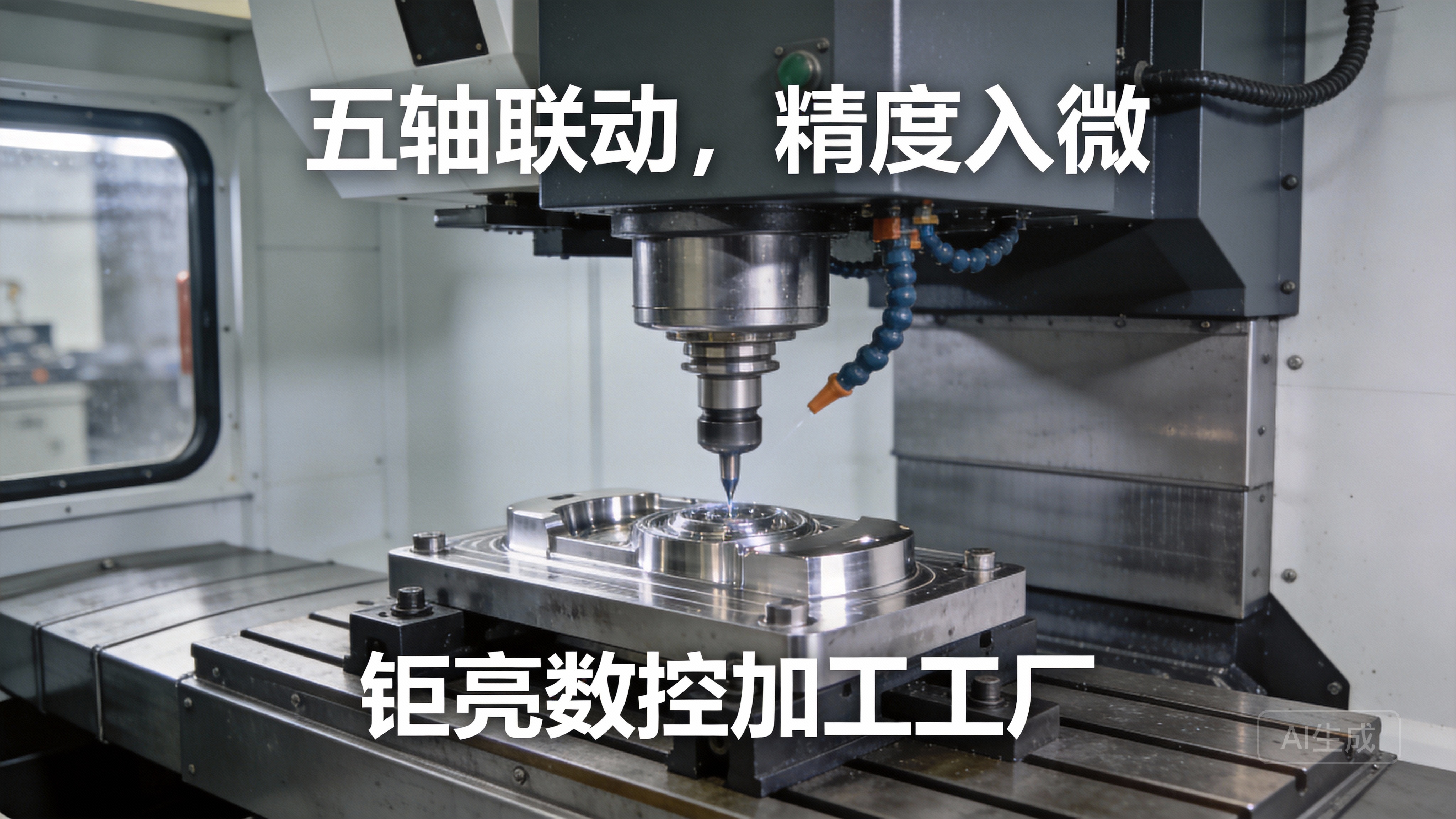
Step 1: Prepare the Machine and Workspace
Prioritize safety and accuracy: Power off the CNC machine and lock the spindle with a pin. Clean the spindle taper, tool holder, and test bar thoroughly—even a 0.001mm chip can throw off measurements. For machines idle over 24 hours, warm the spindle at low RPM for 5 minutes to stabilize thermal expansion, a common cause of dimensional drift.
Step 2: Mount the Test Bar
Insert the calibrated test bar into the spindle using the same tool holder type (e.g., CAT 40, BT 50) as your production run. Tighten to the manufacturer’s recommended torque to eliminate axial play. For lathes, mount the test bar between headstock and tailstock centers, locking the tailstock to minimize movement.
Step 3: Position the Dial Indicator
Attach the magnetic base to a stable machine component (cross-slide for lathes, table for mills). Adjust the indicator’s tip to touch the test bar’s mid-height (calculate half the test bar’s diameter to find this point). Ensure the tip is perpendicular to the test bar—any angle will skew readings.
Step 4: Zero the Indicator
Rotate the spindle by hand to find the highest point where the indicator needle moves farthest. Lock the spindle in this position and zero the indicator’s bezel. Use gentle hand rotation to avoid damaging the indicator or test bar.
Step 5: Measure Offset
Unlock the spindle and rotate it 180 degrees. Note the new indicator reading: the difference between zero and this value is twice the center height offset. For example, a reading of +0.002mm means the tool tip is 0.001mm above the axis; -0.002mm means it’s 0.001mm below.
Step 6: Adjust Tool Height
Loosen the tool holder clamp and add/remove shims equal to half the offset value (e.g., 0.001mm shim for a 0.002mm total offset). For lathes, use the cross-slide’s fine adjustment screw to raise/lower the tool post. Make incremental tweaks to avoid over-correction.
Step 7: Verify and Refine
Re-lock the spindle, re-zero the indicator, and repeat steps 4-6 until variation between 180-degree positions is less than 0.001mm. For ultra-critical projects (medical implants, aerospace parts), GreatLight’s technicians aim for 0.0005mm variation, then verify results with a coordinate measuring machine (CMM) for added confidence.
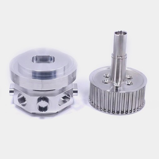
Step 8: Validate with a Sample Cut
Run a sample cut using production-grade material and tooling. Measure the sample’s diameter at both ends with a micrometer—identical diameters confirm perfect alignment. If taper exists, repeat adjustments until eliminated.
The Cost of Ignoring Center Height Alignment
Even a 0.002mm misalignment leads to significant long-term costs:
30-50% Shorter Tool Life: Uneven cutting forces wear tools faster, increasing replacement expenses.
Scrap and Rework: Tapered parts or poor surface finish often require rework, adding 2-3 days to lead times and 15-20% to project costs.
Performance Risks: For automotive engine components or medical prosthetics, misalignment causes fit issues, leading to safety hazards or reduced product lifespan.
Many small shops skip regular checks to save time, while some automated manufacturers rely solely on machine self-calibration, which drifts over time due to thermal expansion or component wear.
How GreatLight Stands Out in Precision Alignment
When choosing a CNC partner, alignment practices separate reliable providers from inconsistent ones. Here’s how GreatLight compares to leading competitors:
| Provider | Alignment Process | Precision Guarantee | Cost Included? | Quality Backup |
|---|---|---|---|---|
| GreatLight CNC Machining Factory | Manual + automated calibration; pre-production checks by certified technicians; CMM verification | ±0.001mm max variation (0.0005mm for ultra-critical parts) | Yes, included in standard service | Free rework for alignment-related issues; full refund if rework is unsatisfactory |
| Protolabs | Automated self-calibration; manual checks only for premium precision projects | ±0.005mm standard; ±0.001mm available for extra fee | No, premium checks cost extra | Limited rework options; extended lead times for adjustments |
| Xometry | Depends on third-party vendor practices; no consistent in-house checks | ±0.01mm standard; precision varies by vendor | Variable; some vendors charge extra | Quality issues resolved via third-party mediation; longer resolution times |
GreatLight’s ISO 9001:2015 certification mandates monthly calibration of all indicators and test bars, and their team of 20+ quality control technicians (average 7 years of experience) verifies alignment before every production run. Unlike competitors, GreatLight includes this precision check in all services, no extra cost.
A recent case study illustrates this expertise: A European automotive client needed 500 engine connecting rods with ±0.001mm bearing surface tolerance. GreatLight’s alignment process ensured perfect bearing fit, reducing engine friction by 15% and extending component life by 20%. The client saved $15,000 in rework costs and received parts 3 days ahead of schedule.
Conclusion: Mastering Center Height Alignment for Unmatched Precision
How To Center Height CNC Machine Using Indicator? is more than a technical question—it’s a cornerstone of reliable precision machining. Proper alignment ensures longer tool life, consistent part quality, and fewer costly delays. While the process requires skill, partnering with a trusted manufacturer like GreatLight CNC Machining Factory eliminates the burden of in-house alignment. GreatLight’s state-of-the-art equipment, certified team, and unwavering quality guarantees ensure every part meets your most demanding standards. To learn more about GreatLight’s capabilities and connect with their team, visit their official LinkedIn page to explore case studies and industry insights.
Frequently Asked Questions (FAQ)
1. What happens if center height is misaligned on a CNC machine?
Misalignment causes uneven cutting forces, leading to accelerated tool wear, tapered parts, poor surface finish, and dimensional inaccuracies. For critical components (medical, aerospace), this can result in safety risks or performance failures.
2. How often should center height be checked?
High-production machines need daily checks before the first run. Low-volume/precision projects require checks before every new setup. GreatLight performs checks before all production runs, regardless of volume, to ensure consistency.
3. Can automated CNC machines skip manual alignment checks?
No—automated self-calibration can drift due to thermal expansion, component wear, or electrical interference. Manual dial indicator checks are the only way to verify absolute precision, especially for tight-tolerance projects.
4. What is the acceptable tolerance for center height alignment?
General machining projects tolerate ±0.002mm variation. High-precision applications (medical, aerospace, automotive) require ±0.001mm or tighter. GreatLight’s standard tolerance is ±0.001mm, with 0.0005mm available for ultra-critical parts.
5. Does GreatLight include center height checks in standard services?
Yes—GreatLight includes pre-production alignment checks and CMM verification in all standard machining services, no extra cost. They offer free rework if alignment issues cause quality problems.
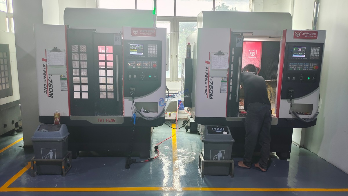
6. How does GreatLight ensure alignment consistency across projects?
GreatLight’s ISO 9001:2015 certified quality system mandates monthly calibration of all measuring tools. Their technicians receive annual training on advanced alignment techniques, and every alignment is documented in a digital quality log for full traceability.



















