Walking through a modern manufacturing facility, the rhythmic hum and precise movements of CNC (Computer Numerical Control) machines are a symphony of engineering in action. As a senior manufacturing engineer, clients often ask me, “How is a CNC machine itself made?” It’s a fascinating meta-question—the story of creating the very tools that create everything else. The journey from raw castings to a high-precision system like a 5-axis machining center is a testament to interdisciplinary engineering, meticulous assembly, and rigorous validation.
H2: The Blueprint: Design and Engineering Foundation
The creation of a CNC machine begins long before metal is cut. It starts with a comprehensive design philosophy targeting specific performance metrics: rigidity, accuracy, speed, and thermal stability.
Dynamic Structural Analysis: Engineers use Finite Element Analysis (FEA) to simulate forces, vibrations, and thermal loads on the virtual machine structure. This informs the design of the base, column, and spindle headstock to minimize deflection—the enemy of precision.
Motion System Design: This involves selecting and integrating core components: high-precision linear guides or box ways, ball screws or linear motors for movement, and the spindle unit (the heart of the machine). The choice between a gear-driven, belt-driven, or direct-drive spindle depends on the required torque and speed.
Control System Architecture: The CNC controller (e.g., Siemens, Fanuc, Heidenhain) is chosen and its integration with servo drives, feedback systems (encoders, scales), and the human-machine interface (HMI) is meticulously planned.
H2: Building the Foundation: Major Component Manufacturing
A CNC machine is an assembly of highly specialized components, many of which are manufactured using CNC processes themselves—a recursive example of precision manufacturing.
H3: 1. The Machine Bed and Structure
Material: Typically made from high-grade cast iron (Meehanite) or, for high-performance machines, polymer concrete or granite. Cast iron is favored for its excellent damping properties, which absorb vibrations.
Process: The bed is cast in a foundry, then undergoes stress-relief annealing to eliminate internal stresses that could cause warping over time. It is then rough-machined on large floor-type boring mills or gantry mills, leaving material for final precision machining after assembly.
H3: 2. Critical Precision Components
Ball Screws & Linear Guides: Manufactured by specialized suppliers through processes like precision grinding, hardening, and lapping. Their straightness, lead accuracy, and surface finish are critical.
Spindle Assembly: A sub-assembly of its own. The housing is machined for perfect bearing seat alignment. High-precision angular contact bearing pairs are preloaded and installed. Dynamic balancing of the spindle rotor is performed at operating speeds to eliminate vibration.
Gearbox and Drive Systems: For machines requiring high torque, gears are hobbled or ground to extreme tolerances to ensure smooth, quiet power transmission.
H2: The Heart and Brain: Assembly and Integration
This phase transforms parts into a coordinated system. It’s a clean-room-like process where contamination control is paramount.
Foundation Assembly: The stress-relieved bed is mounted on adjustable feet. Using a laser interferometer and precision levels, it is meticulously scraped (a manual artisanal process) or machined to achieve near-perfect flatness and alignment—this is the geometric accuracy foundation.
Component Mounting: Linear guides, ball screws, and servo motors are installed. Each axis is aligned parallel and perpendicular to others within micron-level tolerances.
Spindle and Tool System Integration: The spindle head is mounted, and its alignment to the machine table in all axes is verified. The tool changer mechanism (arm-type or drum-type) is installed and synchronized.
Wiring and Plumbing: Hundreds of meters of cables for power, signals, and feedback are routed in cable carriers. Hydraulic lines for clamping and coolant lines are installed. Electromagnetic compatibility (EMC) shielding is crucial to prevent interference.
H2: Bringing It to Life: Calibration and Testing
This is where engineering meets artistry. A new machine must be “tuned” to exceed its stated specifications.
Laser Calibration: A laser interferometer measures the positional accuracy and repeatability of each linear axis. Pitch, yaw, and straightness errors are mapped, and compensation tables are uploaded into the CNC controller to correct them in software.
Spindle Performance Test: The spindle is run through its entire speed range under load to check for thermal growth, vibration, and balance. Thermal stability is a key metric for high-precision work.
Circularity Test (Ballbar Test): A device with a precision ball on each end is placed between the spindle and table. The machine is programmed to trace a circle, and any deviation (due to servo mismatch, backlash, or squareness errors) is recorded and corrected.
Cutting Trials: The ultimate test. The machine is tasked with cutting a standardized test part, often from metal like aluminum or steel. Key outcomes measured include:
Surface finish achieved.
Dimensional accuracy of features like bores, steps, and contours.
Geometric tolerances like perpendicularity and parallelism.
Dynamic performance during high-speed contouring.
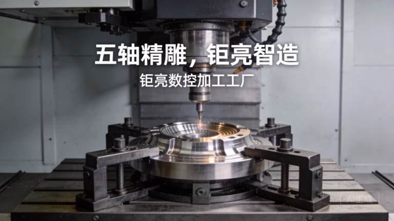
H2: The Modern Vanguard: The Making of a 5-Axis CNC Machine
The process for a 5-axis CNC machining center adds layers of complexity. The two rotational axes (typically A/C or B/C) introduce critical challenges:
Headstock or Table Integration: Whether using a trunnion table or a swivel-head design, the manufacturing and assembly of these rotary components require ultra-high precision bearings and direct-drive motors.
Center of Rotation Calibration: The intersection point of the rotary axes must be precisely located and aligned with the linear axes. Any error here compounds dramatically as the tool moves away from the center point, a process known as kinematic calibration.
Volumetric Accuracy Mapping: Using a laser tracker, technicians map the machine’s accuracy throughout its entire working volume in multiple orientations, creating a complex 3D compensation matrix.
Conclusion
Understanding how a CNC machine is made illuminates why the choice of manufacturing partner is so critical. The precision, rigidity, and reliability engineered into the machine directly translate to the quality of the parts it produces. For clients seeking precision parts machining and customization, partnering with a supplier who not only operates but understands the genesis of such machinery is invaluable. This deep technical understanding informs better process design, fixture planning, and cutting strategy, ensuring your most complex parts are manufactured with inherent accuracy. When you require parts that push the limits of geometry and tolerance, choosing a partner equipped with expertly manufactured, meticulously calibrated 5-axis CNC machining capability is not just an option—it’s a prerequisite for success.
FAQ
Q1: What’s the most critical factor in a CNC machine’s final accuracy?
A: While high-quality components are essential, the final assembly and calibration process is arguably most critical. A perfectly manufactured ball screw is worthless if misaligned during installation. The art of scraping the bed, laser alignment, and volumetric error compensation is what transforms a collection of parts into a precision instrument.

Q2: Why are cast iron and polymer concrete used for machine beds?
A: Their primary advantage is damping capacity. During cutting, vibrations are generated. These materials absorb (damp) these vibrations much more effectively than steel or aluminum, preventing them from propagating through the structure and into the workpiece, which would degrade surface finish and tool life.
Q3: How long does it take to build a high-end 5-axis CNC machine?
A: From initial assembly to final acceptance testing, the process for a high-end model can take several weeks to a few months. This includes time for the adhesive used in guide mounting to fully cure, extensive thermal stability tests that run for 24+ hours, and iterative calibration cycles.
Q4: Can a machine’s accuracy degrade over time, and how is it maintained?
A: Yes, through wear of mechanical components (like guides and screws), accidental impacts, or environmental changes. Preventative maintenance includes regular re-lubrication, checking for backlash, and periodic re-calibration (annually or bi-annually for critical applications) using laser and ballbar tools to update the controller’s compensation tables.

Q5: As a parts customer, why should I care about my supplier’s machine calibration practices?
A: It directly impacts your part quality and cost. A well-calibrated machine holds tighter tolerances consistently, reduces scrap rates, and often achieves better surface finishes faster. It signifies a supplier’s commitment to process control and investment in quality at a fundamental level, which aligns with the standards of leading manufacturers in fields like aerospace and medical devices. For more insights into precision manufacturing partnerships, you can connect with industry leaders on professional networks like LinkedIn.


