At its core, the operation of a CNC (Computer Numerical Control) machine is a brilliant symphony of digital instruction and physical execution, transforming raw material into intricate, high-precision components. This process has become the backbone of modern manufacturing, enabling the repeatable production of complex parts that would be nearly impossible or prohibitively expensive to make manually. For clients seeking precision parts machining and customization, understanding how CNC machines work demystifies the manufacturing process and highlights the technological sophistication behind a reliable supplier’s capabilities.
The journey of a CNC-machined part begins long before the first tool touches the material. It starts with a digital blueprint.
H2: The Digital Foundation: From CAD Model to Machine Language
Every precision part originates as a concept, which is crystallized into a 3D Computer-Aided Design (CAD) model. This model defines the part’s exact geometry, dimensions, and tolerances. The CAD file is then imported into Computer-Aided Manufacturing (CAM) software. This is where the manufacturing engineer’s expertise becomes critical. The CAM software is used to:
Plan Toolpaths: The engineer selects the appropriate cutting tools (end mills, drills, etc.) and defines their precise paths across the material to carve out the desired shape.
Set Parameters: Crucial machining parameters are inputted, including spindle speed (RPM), feed rate (how fast the tool moves), depth of cut, and coolant application.
Generate G-Code: The CAM software translates all this planning into G-code, the universal programming language for CNC machines. G-code is a sequential set of alphanumeric instructions that dictate every movement of the machine—every line, arc, pause, and tool change.
This digital preparation phase is where a partner like GreatLight adds immense value. Their engineering team doesn’t just blindly generate code; they optimize toolpaths for efficiency, minimize tool wear, prevent collisions, and strategize to achieve the best possible surface finish and dimensional accuracy, especially when leveraging their advanced 5-axis CNC machining capabilities for geometrically complex parts.

H3: The Physical Execution: Anatomy of a CNC Machine in Action
Once the G-code is loaded into the CNC machine’s controller, the physical magic begins. A standard CNC machining center consists of several key subsystems working in concert:
1. The Controller & Drive System: The “Brain and Nerves”
The controller is a dedicated industrial computer that reads the G-code instructions. It sends precise electrical signals to servo motors or stepper motors that drive the machine’s mechanical components. A closed-loop feedback system continuously monitors the position of the tool and workpiece using linear scales or rotary encoders, making real-time corrections to ensure movement accuracy to within microns. This is fundamental to achieving the high precision GreatLight maintains, often down to ±0.001mm.
2. The Mechanical Structure: The “Body”
This includes the rigid frame, guideways, and ball screws. The frame provides stability to dampen vibrations, while the guideways allow for smooth, precise linear motion. Ball screws convert the rotary motion of the motors into precise linear movement of the machine axes (typically X, Y, and Z).

3. The Tooling System: The “Hands”
The cutting tool, held in a collet within the spindle, is the point of contact. The spindle, a high-precision motor, rotates the tool at speeds that can reach tens of thousands of RPM. An Automatic Tool Changer (ATC) allows the machine to switch between dozens of different tools from a carousel without manual intervention, enabling complex operations in a single setup.
4. The Workholding System: The “Grip”
The raw material (metal, plastic, composite) must be securely fastened to the machine bed or a rotary table. This is done using vises, clamps, or custom fixtures. Precise and rigid workholding is non-negotiable; any movement or vibration during cutting will ruin the part’s accuracy.
H4: The Machining Process: Material Removal in Motion
With everything in place, the cycle starts. The controller instructs the drive system to move the tool and/or workpiece along the programmed paths. As the spinning tool engages with the stationary workpiece, it shears away small chips of material. This process can involve various operations:
Milling: A rotating cutting tool moves along multiple axes to remove material.
Turning: The workpiece rotates while a stationary cutting tool traces its exterior (common in lathes).
Drilling & Tapping: Creating holes and internal threads.
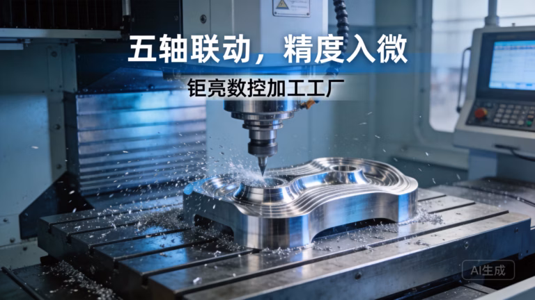
5-Axis Machining: The tool can approach the workpiece from virtually any direction in a single setup, allowing for the creation of incredibly complex, organic geometries—a specialty at facilities like GreatLight CNC Machining Factory.
Coolant is continuously flushed over the cutting area to dissipate heat, lubricate the cut, and flush away metal chips, ensuring tool longevity and part quality.
H3: The Role of Advanced Capabilities: 5-Axis and Beyond
While 3-axis machines (moving in X, Y, Z) are common, the true frontier for complex parts is 5-axis CNC machining. Here, in addition to the three linear axes, two rotational axes (typically A and B) allow the cutting tool to tilt and rotate relative to the workpiece. This enables:
Machining of five sides of a part in one setup, drastically reducing lead time and improving accuracy by eliminating repositioning errors.
Use of shorter cutting tools, which can operate at higher speeds with less vibration.
Machining of undercuts and complex contours that are inaccessible to 3-axis machines.
This advanced capability is what allows manufacturers like GreatLight to tackle the most challenging prototypes and production parts for industries such as aerospace, medical, and automotive.
Conclusion
So, how does a CNC machine work? It is a seamless integration of digital intelligence and mechanical precision. It starts with a meticulous digital plan (CAD/CAM), which is translated into a machine-readable language (G-code). This code then commands a sophisticated electromechanical system to execute precise, coordinated movements, removing material layer by layer until a finished, high-tolerance component emerges. The entire process is automated, repeatable, and scalable. For businesses, partnering with a manufacturer that masters every link in this chain—from expert CAM programming and optimal toolpath strategy to operating advanced multi-axis machinery and implementing rigorous in-process quality checks—is the key to transforming innovative designs into reliable, high-performance physical products. The sophistication of this process underscores why choosing an expert partner for your precision parts machining needs is not just a procurement decision, but a critical strategic investment in your product’s quality and success.
Frequently Asked Questions (FAQ)
Q1: What is the main advantage of CNC machining over manual machining?
A: The primary advantages are precision, repeatability, and complexity. CNC machines can consistently produce parts with tolerances in the micron range, something extremely difficult to achieve manually. Once a program is verified, it can produce thousands of identical parts. Furthermore, CNC can easily create complex 3D shapes that are impractical or impossible to make manually.
Q2: How accurate can CNC machines be?
A: The accuracy depends on the machine’s quality, calibration, and the operator’s skill. Standard industrial CNC machines typically hold tolerances of ±0.005 inches (±0.127 mm). High-precision machines, like those used by specialized shops including GreatLight, can consistently achieve tolerances of ±0.0005 inches (±0.0127 mm) or better, with some applications reaching ±0.001mm for critical features.
Q3: What materials can be processed by CNC machines?
A: CNC machines are incredibly versatile and can process a vast array of materials, including:

Metals: Aluminum, stainless steel, titanium, brass, copper, alloy steels, magnesium.
Plastics: ABS, Polycarbonate, Nylon, PEEK, Delrin.
Composites: Carbon fiber, G10.
Wood and Foams.
The key is selecting the correct cutting tools, speeds, and feeds for the specific material.
Q4: What is the difference between 3-axis, 4-axis, and 5-axis CNC machining?
A: The “axes” refer to the directions in which the cutting tool or workpiece can move.
3-Axis: Tool moves in linear X, Y, Z directions. Ideal for parts without complex undercuts.
4-Axis: Adds a rotary axis (usually the A-axis), allowing the workpiece to rotate. Excellent for machining features around a cylinder.
5-Axis: Adds a second rotary axis (e.g., B-axis), allowing the tool to approach the workpiece from any angle. This is essential for complex, sculpted parts like impellers, turbine blades, and aerospace components, and is a core service for advanced manufacturers.
Q5: Is CNC machining suitable for both prototyping and mass production?
A: Absolutely. It is one of the most flexible manufacturing processes. For prototyping, it allows for rapid iteration with high-fidelity materials. For mass production, its automation and consistency make it highly efficient. The same digital file can be used for both stages, ensuring a seamless transition from prototype to final product. To see how industry leaders leverage this flexibility, you can explore the professional network of experts on platforms like LinkedIn.


