
Heat Shrink End Cap Rapid Prototype
A heat shrink end cap seals cable ends, connectors, and wire bundles when it is heated and recovers. A rapid prototype is the functional sample you test before tooling. This page explains what actually drives fit and sealing, and how to choose a process for your geometry.
In this article
- 1
- 2
- 3
- 4
- 5
- 6
- 7
- 8
How a heat shrink end cap actually seals
A heat shrink end cap is a polymer sleeve with a closed dome. It is supplied in an expanded state, slipped over a cable end or connector, then heated. The polymer chains relax and the cap recovers radially, and usually a little longitudinally, clamping the substrate underneath.
The seal is mechanical, not adhesive. Recovery generates contact pressure between the inner wall and the cable jacket. That pressure, plus the creep resistance of the polymer, keeps water and dust out.
This is why geometry matters more than wall thickness alone. A cap that is 0.2 mm too loose will still look right on a bench and fail an immersion test.
Recovery is also anisotropic. Most extruded and expanded tubing recovers far more in the radial direction than the axial one. Your prototype has to reflect that ratio, or the recovered length will be wrong.
What a heat shrink end cap rapid prototype has to prove
A prototype is not a pretty model. It is the part that tells you whether the design works before you commit to a mold. For an end cap, that means four measurable things.
Expanded inner diameter controls how easily the cap slides over the cable. If it is undersized, installation damages the jacket or the cap tears at the dome. If oversized, the recovered wall may not grip.
Wall thickness distribution decides sealing pressure and dielectric strength. A uniform 1.0 mm wall behaves very differently from a nominal 1.0 mm wall that thins to 0.6 mm at the dome transition.
Recovered dimensions set the installed profile. Cable assemblies are often routed through tight spaces, so recovered outer diameter and recovered length both matter.
Finally, the prototype validates the material. A cap that recovers correctly but crazes after 500 hours at 105 °C is not a working design.
- 1Expanded IDControls installation force and interference fit.
- 2Wall thicknessSets contact pressure and dielectric strength.
- 3Recovered OD and lengthSets clearance and routing.
- 4Material behaviorShrink ratio, gel content, and aging.
Matching the process to the geometry you need
Not every end cap prototype belongs on a CNC. The right process follows from the feature set and the number of units you need to test.
Simple round caps with one internal diameter are cheap to vacuum cast or print. Once the cap has internal ribs, a stepped bore for multiple cable sizes, or a keyway to clock the cap on a connector, the tooling cost of a printed or cast route climbs quickly, and the dimensional spread widens.
Machined prototypes hold the tightest tolerance on critical diameters. We normally work to ±0.005 mm on a machined prototype where the drawing calls for it, and Ra 0.8–1.6 μm on sealing surfaces.
The catch is that machining removes material rather than expanding it. A machined cap is a rigid replica of the recovered shape, not a shrinkable part. You test fit and clearance, not recovery.
Where 5-axis machining changes the answer
An end cap looks like a turned part until you look inside. Internal sealing lips, angled lead-ins, and offset keyways cannot all be reached from one direction with a 3-axis machine.
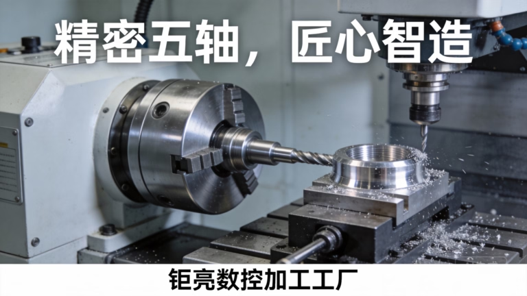
A 5-axis machining center reaches those features in one setup. That matters for two reasons: no split lines across a sealing surface, and no re-fixturing error between the outside profile and the internal bore.
Our shop runs 16 simultaneous 5-axis machining centers, plus 16 mill-turn centers for caps that are mostly turned with a few milled features. Maximum processing size is 4,000 mm, which covers any realistic cable end cap.
For a dome-shaped cap in POM or PA, a mill-turn route usually wins. Turn the outer profile and the bore, then mill the keyway and the lead-in chamfer without a second setup.
Material choice for a machined end cap prototype
If you machine the prototype, you are not using the production compound. Heat shrink caps are cross-linked polyolefin, and cross-linked material does not machine into a clean thin wall.
So the question becomes which machinable plastic best mimics the stiffness and friction of your production cap. This is a judgment call, and it depends on what you are testing.
For a fit check where the cap slides over a jacket, POM gives low friction and good dimensional stability. PA adds toughness if the cap will be flexed during installation.
For high-temperature checks, PEEK holds properties well above 200 °C, but it costs far more and machines slower. Use it only when the thermal case is the point of the test.
If the test is about dielectric behavior rather than fit, the material choice matters less than wall thickness consistency, and a machined part with a uniform wall is a good stand-in.
Tolerance and inspection on a sealing part
An end cap has two critical dimensions: the expanded inner diameter that sets the fit before recovery, and the wall thickness at the dome transition where stress concentrates.
On a machined prototype we hold ±0.005 mm where the drawing calls for it. In imperial terms that is ±0.0002 in. Not every feature needs that. Chasing tight tolerance on a non-sealing surface adds cost without adding information.
Inspection follows the same logic. We check raw material on arrival, monitor dimensions in process, and inspect 100% before shipment. Reports are available on request.
For end caps, the useful report is a dimensional layout on the sealing diameters plus a wall thickness map around the dome. A single spot measurement hides the thin section that will fail first.
Post-processing and what it does to the prototype
Finishing a prototype is not cosmetic. On an end cap, surface condition changes both friction and sealing.
Bead blasting a sealing surface raises friction and can make installation harder. Polishing lowers it and makes the cap slide on more easily, which may or may not match production.
For a machined prototype, a light tumble or brush finish usually gives a surface closer to extruded tubing than a machined finish does.
Laser marking is useful for identifying prototype revisions, with a minimum character height of 1.5 mm. Marking in a non-sealing area keeps it from creating a leak path.
If the cap will be tested outdoors, anodizing does not apply to plastics. Keep the finish decision tied to what the test is measuring.
Rapid prototype process comparison for end caps
Pick the row that matches your feature set and test goal.
| Process | Best for | Typical tolerance | Watch out for |
|---|---|---|---|
| CNC machining | Rigid fit checks, tight bores | ±0.005 mm on critical diameters | Cannot demonstrate shrink recovery |
| Vacuum casting | Simple round caps, 10–50 units | ±0.1 mm on cast features | Silicone tool wear shifts size |
| 3D printing | Early form checks, complex shells | ±0.1 mm and up | Layer lines on sealing surfaces |
| Prototype tooling | Shrink behavior in real resin | Tool-dependent | Cost and lead time jump |
Which route to take
If you need to prove shrink recovery and installed sealing, go to prototype tooling in the real compound. If you need to prove fit, clearance, and connector interface geometry this week, machine it in POM or PA and accept that recovery is not part of the test.
Common questions
Can a machined cap show how the part shrinks?
No. Machining cuts the recovered shape out of solid stock, so the part is already at its final size. It cannot recover because the polymer was never cross-linked or expanded.
Use a machined cap to check fit, clearance, and connector interface. Use prototype tooling when the recovery ratio itself is the thing under test.
What wall thickness should a prototype have?
Match the production wall at the sealing zone and at the dome transition. Those two areas set contact pressure and stress concentration.
A uniform wall is easy to machine and easy to measure, which makes it a good baseline. Note any place where the production part thins out, and expect the prototype to behave differently there.
How tight should the bore be?
Tight enough to grip, loose enough to install without tearing the jacket. On a machined prototype we hold ±0.005 mm on critical diameters so you can test both ends of the tolerance band.
Order two or three bore sizes rather than one. The extra cost is small and it tells you where the fit window actually opens and closes.
Is 3D printing good enough for an end cap prototype?
For an early form check, yes. Layer lines and lower dimensional accuracy make it a poor choice for a sealing surface.
If the cap has to hold pressure or pass an immersion test, print it only to confirm the shape, then move to machining or tooling for the functional sample.
What do you need to quote this?
A 3D file or drawing, the expanded and recovered dimensions if you have them, the material or its closest machinable equivalent, and the quantity.
We return a quotation and a free DFM analysis within 12 hours, and production can start within 24 hours of approval. Parts typically ship in 3–5 days.
Can you sign an NDA?
Yes. Uploads are handled as confidential, and an NDA is available on request before you send files.
If the design is under a customer NDA, tell us at the quote stage and we will route the work accordingly.
Send us your end cap drawing
Upload the file and we will come back with a quotation and a DFM review of your sealing diameters and wall thickness.
12-hour quoteNo minimum order quantity100% inspection
More from the shop floor
We publish setup notes, tooling trials and inspection data from the factory floor.











