
ODM CNC Milling Turning, Explained for Engineers
This page is for design and manufacturing engineers who need machined parts in days, not weeks. It covers where lead time actually goes in ODM CNC milling turning, what shop capability makes speed repeatable, and when a build-to-print job is the better call.
In this article
- 1
- 2
- 3
- 4
- 5
- 6
Where lead time actually goes in ODM CNC milling turning
Cutting metal is rarely the bottleneck. On a typical milled or turned job, spindle time is a small share of the calendar. The rest is programming, workholding, setup changeover, tool proving, first-article inspection, and queueing for a machine that is already booked. A shop that quotes 3–5 days has usually removed those hours, not found a magic feed rate.
This matters when you compare quotes. Two suppliers can use the same 6061-T6 block and the same tolerance, yet one delivers in three working days and the other in twelve. The difference sits in the non-cutting work: how fast CAM is generated, whether fixtures already exist, and whether inspection runs in parallel with the next setup.
ODM changes the equation further. In ODM CNC milling turning, the supplier is not just handed a frozen drawing. They review the model, flag features that will force extra setups, and often propose a small change that cuts two operations. A 0.5 mm fillet change or a looser corner radius can remove an EDM step entirely.
So treat speed as a process property, not a machine property. Ask what happens between the moment your file lands and the moment chips fly. That answer predicts the delivery date better than any spindle RPM figure.
Why machine diversity decides your delivery date
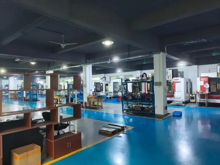
A shop with only 3-axis vertical mills will farm out every turned feature. That single outsourced operation can add days and a second setup tolerance stack. Fast-turn capability comes from owning the whole mix: mills, lathes, mill-turn centers, and enough simultaneous 5-axis capacity to hit compound angles without re-fixturing.
Consider a bracket with angled pockets. On a 3-axis machine it may need four or five setups, each with a touch-off and a prove-out. A 5-axis center reaches the same geometry in one setup. Setup count, not spindle speed, is what usually separates a two-day part from a six-day part.
Size range matters just as much. A shop that tops out at 600 mm cannot help with a 2 m frame, and one that only runs large travels wastes time dialing in small parts. A park that spans compact 500 × 500 × 450 mm work up to 4,000 mm travel covers both without sending work out.
For turned parts, mill-turn centers remove a second operation. Features that would otherwise be interpolated on a mill, or drilled on a separate machine, come off in one chucking. That also tightens concentricity, since the part never leaves the spindle.
- 116 simultaneous 5-axis centersCompound angles in one setup instead of four.
- 216 mill-turn centersMilled features on turned parts without re-chucking.
- 34,000 mm maximum processing sizeLarge frames and long shafts stay in-house.
- 4Ø400 mm rotary tableIndexed work on round and prismatic parts.
What fast turning and milling actually requires
Programming speed comes from a CAM library that already knows the shop's tools, holders, and post-processors. When a programmer rebuilds toolpaths from scratch for every job, the quote-to-chip gap stretches. Reusable templates and stock fixtures are what let production start within 24 hours of a released model.
Workholding is the quiet cost. A custom soft jaw or a dedicated plate can take a day to make. Shops built for quick turns keep modular vises, collet systems, and standard pallets so a new part drops into an existing grid. If a job needs a bespoke fixture, build that time into your plan.
Tolerance drives method, not the other way around. Holding ±0.005 mm on a small turned part is routine on a good lathe. Holding it across a 1,000 mm milled face is a different problem: thermal drift, tool wear, and fixturing all enter. Split the drawing into the features that truly need tight limits and let the rest run at Ra 1.6–3.2 μm.
Surface finish is a scheduling input too. A Ra 0.2–0.8 μm requirement may mean a separate finishing pass or a polishing step after machining. That extra step is fine, but it should be visible in the plan rather than discovered at inspection.
Material choice and how it shifts the schedule
Aluminium is the default for fast turns. Grades like 6061-T6, 6082, and 7075 cut quickly, hold tolerance well, and are widely stocked. If your part is a housing, bracket, or fixture plate, 6061-T6 is usually the fastest route to a functional part without sacrificing strength.
Stainless and steel slow things down, but predictably. 303 and 304 turn cleanly; 316L and 17-4PH need more careful speeds and can work-harden if the toolpath is wrong. Alloy steels such as 4140 and 4340 are fine for shafts and load-bearing parts, though they push cycle times up compared with aluminium.
Titanium and nickel alloys are the long pole. Ti-6Al-4V (TC4) and Inconel cut slowly, wear tools fast, and need rigid setups. They are the right answer for high-temperature or high-strength parts, but they should not be on the critical path unless the design truly needs them.
Plastics and copper alloys sit in between. POM and PEEK machine well with sharp tooling and good chip evacuation; copper and brass turn fast but are gummy, so chip control matters. Match the material to the function first, then to the schedule.
When ODM design input saves more time than it costs
ODM input pays off when a design has features that are expensive to machine but cheap to change. A deep pocket with a sharp internal corner forces a small tool and a long cycle. Increasing the corner radius to match a standard end mill can cut cycle time noticeably with no functional loss in most brackets.
The same logic applies to bosses, ribs, and undercuts. A slightly thicker boss can remove the need for a support fixture. A relocated hole can avoid an angled setup. These are not cosmetic tweaks; each one removes an operation from the routing.
ODM input is less useful when the design is already frozen by a customer drawing, a mating interface, or a regulatory form. In those cases the shop should machine to print and flag manufacturability issues without changing geometry. Knowing which situation you are in prevents wasted review cycles.
A practical rule: if a feature exists only because the CAD was easy to draw, it is a candidate for ODM input. If it exists because something else bolts to it, leave it alone.
ODM versus build-to-print: which route fits your job
Use this to pick the engagement model before you send files.
| Situation | Better route | Why | Watch out for |
|---|---|---|---|
| Concept model, geometry still moving | ODM | Shop can suggest changes that cut setups | Changes need your sign-off |
| Frozen drawing with mating interfaces | Build-to-print | No room to alter geometry | Flag DFM issues, do not change |
| Complex angled features | ODM with 5-axis | One setup replaces four | Confirm reach and rigidity |
| Simple turned shaft, tight OD | Build-to-print | Turning is already one operation | Check concentricity callouts |
| Titanium or Inconel part | ODM, early review | Toolpath and setup choices dominate time | Do not rush tool selection |
| Cosmetic anodized housing | Either | Finish step is separate from machining | Finish adds a pass, not a week |
The clear call
If your geometry is still open and you want the shortest route from model to part, choose ODM CNC milling turning and let the shop remove setups before cutting. If the drawing is frozen by a mating part or a spec, choose build-to-print and ask only for a manufacturability flag. Mixing the two without saying which one you want is what causes rework.
Questions engineers ask before sending files
Does ODM mean the shop owns my design?
No. ODM here means the supplier contributes manufacturability input on your design; ownership stays with you.
Uploads are handled as confidential, and an NDA is available on request before you share models.
How tight a tolerance can a fast turn hold?
On small turned parts, ±0.005 mm is routine on a good lathe. Across long milled faces it is harder because thermal drift and tool wear enter.
Mark only the features that need tight limits. Letting the rest run at Ra 1.6–3.2 μm keeps the schedule realistic.
What file format should I send?
A 3D model plus a drawing with critical dimensions and finish callouts is the clearest package. STEP is a safe neutral format.
If only a model exists, say so. The DFM review will flag the dimensions that need a stated limit.
Can I get one prototype and then a production run?
Yes. There is no minimum order quantity, so the same shop can run one prototype and later a 10,000+ part batch.
Keeping both in one shop avoids re-qualifying tooling and fixtures for the production run.
Which certifications matter for my industry?
ISO 9001:2015 covers general quality systems. IATF 16949:2016 applies to automotive, ISO 13485:2016 to medical devices, and ISO 27001:2022 to information security.
Tell the shop your industry up front so the right controls are applied from the first article.
What slows a job down most often?
Missing or ambiguous drawing callouts, and a design that needs a custom fixture. Both force a stop-and-ask cycle.
A short DFM call before release usually removes more delay than any machining change.
Send the model, get a manufacturability answer back
Share your 3D model or drawing and we will return a quotation with a free DFM analysis within 12 hours. Production can start within 24 hours of release, and parts ship in 3–5 days.
12-hour quoteFree DFM analysisNo MOQ100% inspection before shipment
Follow GreatLight
We publish setup notes, tooling trials and inspection data from the factory floor.











