
Design Focused Rapid Tooling ODM: How Design and Tooling Run Together
This page explains what design focused rapid tooling actually changes in a development cycle, which parts benefit, and where the model stops paying off. It is written for mechanical engineers and sourcing teams who have to choose a manufacturing route, not a slogan.
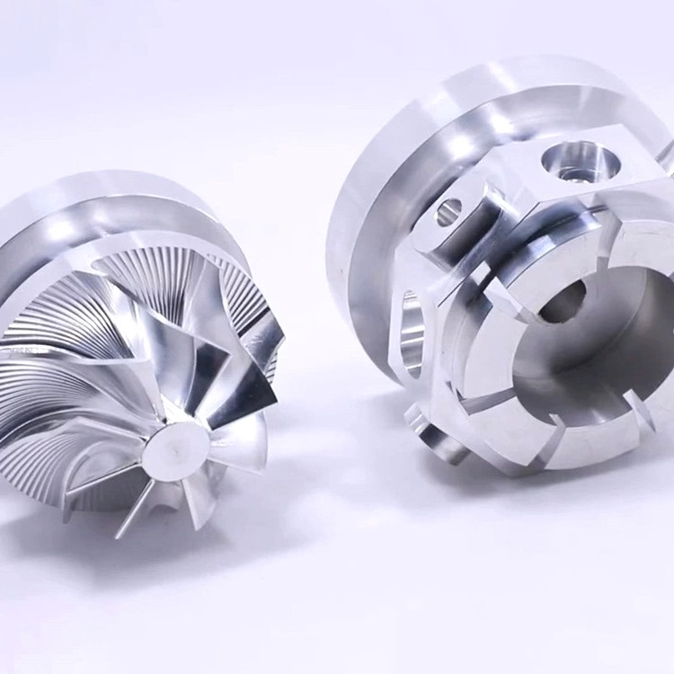
What Design Focused Rapid Tooling ODM Means in Practice
Design focused rapid tooling ODM is a working arrangement, not a service label. The tool builder and the part designer sit in the same loop from the first CAD review. Geometry, draft, wall thickness, gate position and machining allowance get settled before metal is cut, so the first trial part is already close to the drawing.
In a conventional sequence, the print goes out, a tool shop quotes it, the tool is built, and the first shots reveal problems. Each round trip costs days and sometimes a tool weld. Design focused rapid tooling moves that discovery upstream, where a change to a 2 mm fillet costs a modelling minute instead of a week.
The ODM part matters too. We are not only cutting a cavity. We take the design intent, propose the process route, run the prototype, and hand back parts plus a report on what should change for volume. That is why the model suits low-volume bridge production and functional prototypes rather than one-off display models.
The output is a part you can test under real load. For an aluminum housing or a stainless bracket, that means the prototype and the eventual production part share the same process family, so test results transfer instead of being thrown away.
- 1Upstream DFMTolerance, draft and datum review before tool cutting
- 2One process familyPrototype and production parts behave alike
- 3Reported changesYou get the revision list, not just the parts
Why the Conventional Hand-Off Loses Weeks
The wall between design and tooling is where schedules die. A designer works to nominal CAD. A toolmaker works to a block of steel that shrinks, warps and wears. Neither is wrong, but the mismatch only shows up at first article, when the tool is already expensive to change.
Shrinkage is the clearest example. Aluminum die casting alloys such as ADC12 pull roughly 0.4 to 0.7 percent depending on wall thickness and gate layout. If nobody adjusts the cavity for that before cutting, a 200 mm dimension can land 1 mm off and the whole tool needs rework.
Machining allowance is the second trap. A casting that will later be faced and bored needs stock left in the right places. Add it after the tool exists and you may run out of material on one face while wasting material on another.
Fixturing is the third. A part that cannot be held rigidly during finishing will move under cutting load, and no tolerance callout survives that. Datum strategy belongs in the design review, not in the shop at 2 a.m.
- 1ShrinkageADC12 pulls 0.4–0.7 percent; compensate before cutting
- 2Stock allowanceLeave material only where finishing will remove it
- 3Datum strategyDecide clamping before the first operation
Which Parts Suit Design Focused Rapid Tooling
The model earns its keep when geometry is complex, quantity is low to mid, and the material is unforgiving. Precision metal parts fit best: aluminum die-cast housings, stainless steel brackets, titanium implant components, Inconel fixtures. These are the parts where a late change is expensive and a wrong first article is worse.
Volume is the other filter. Bridge tooling makes sense for runs from a single prototype up to a few thousand parts, where hard tooling would sit idle before it pays back. Above that, the economics shift toward dedicated production tooling with its own qualification cycle.
Part size matters less than feature density. A 4,000 mm frame with simple faces is easier than a 60 mm manifold with nine intersecting bores. Deep ribs, thin walls, undercuts and tight true-position callouts are what drive the design review.
If your part is a flat plate with four holes and a ±0.1 mm tolerance, this route is overkill. Send it to a standard 3-axis job and save the engineering hours.
- 1Good fitComplex housings, brackets, implant and fixture work
- 2Good fitPrototype to a few thousand parts
- 3Poor fitSimple flat parts with loose tolerance
- 4Poor fitVery high annual volume on one geometry
How DFM and Machining Interleave on a Real Job
A workable sequence starts with a CAD and STEP file, not a drawing alone. We check wall thickness, draft angle, corner radii and tolerance stack against the intended process. A quotation and free DFM analysis go back within 12 hours, and production can start within 24 hours once the route is agreed.
Roughing comes next, often on a 3-axis machine where the geometry allows it. Finishing moves to simultaneous 5-axis when the part has compound angles, deep pockets or features on five faces. We hold 16 simultaneous 5-axis machining centers, 12 four-axis mills, 27 three-axis machines and 16 mill-turn centers for exactly this split.
Inspection is not a final step, it is a running one. Raw material certificates are checked on arrival, in-process dimensions are monitored at each setup, and 100 percent inspection runs before shipment with reports on request. Tolerance capability reaches ±0.005 mm and surface finish from Ra 0.2–0.8 μm when the drawing calls for it.
Finishing closes the loop: anodizing, electroless nickel, powder coating, bead blasting, laser marking with a 1.5 mm minimum character height. Doing this in-house keeps the prototype and the bridge run on the same cosmetic standard.
- 15-axis16 simultaneous centers for compound geometry
- 2Mill-turn16 centers for shaft and housing features in one setup
- 3InspectionMaterial, in-process and final checks
Where the Model Breaks Down
Design focused rapid tooling is not a shortcut around physics. If the part needs a 0.3 mm wall in a die-cast alloy, the answer is no, and no amount of early review changes that. Thin walls under 0.8 mm in aluminum casting are a real risk of cold shut and porosity.
It also does not replace a production tool qualification. Bridge tooling may use different steel, a simpler cooling layout and a single cavity. Parts are dimensionally representative, but tool life and cycle time are not. Plan a separate qualification before you commit to full volume.
Confidentiality is a practical boundary as well. Sending CAD to any supplier exposes your geometry. We work under NDA on request and treat uploads as secure and confidential, but you should still decide what leaves your network and when.
Finally, the model needs your design owner on the call. If every DFM note has to travel through three people, the loop slows to the speed of the slowest approver and the advantage disappears.
- 1Wall thicknessBelow 0.8 mm in cast aluminum, expect porosity risk
- 2Tool lifeBridge tooling is not a production tool
- 3Approval speedOne design owner keeps the loop short
Choosing a Route by Part and Volume
Use this to pick a route before you request quotes.
| Part profile | Volume | Suggested route | Why |
|---|---|---|---|
| Aluminum housing, complex ribs | 1–500 | Design focused rapid tooling | Shrinkage and draft fixed before cutting |
| Stainless bracket, tight true position | 50–2,000 | Rapid tooling plus 5-axis finishing | Datum strategy decided in review |
| Flat plate, four holes, ±0.1 mm | 1–100 | Standard 3-axis machining | No tooling economics to justify |
| Titanium implant component | 1–200 | Rapid tooling with full traceability | Material cost makes scrap expensive |
| High-volume single geometry | 10,000+ | Dedicated production tooling | Bridge tool life becomes the limit |
When to Choose This Route and When Not To
Choose design focused rapid tooling when geometry is complex, volume sits between one piece and a few thousand, and a late design change would be costly. Choose standard machining for simple loose-tolerance parts, and go straight to dedicated production tooling once annual volume passes the point where bridge tool life becomes the constraint.
Questions Engineers Ask Before Committing
How early do you need the CAD file?
Send the STEP or native CAD as soon as the functional requirements are frozen, even if finishes and tolerances are still open.
Early files let us flag wall thickness, draft and datum issues while changes are still cheap. A quotation and free DFM analysis come back within 12 hours.
Can you hold ±0.005 mm on a rapid tooled part?
Yes, on machined features. We machine to ±0.005 mm where the drawing requires it, with surface finish from Ra 0.2–0.8 μm on finished faces.
Cast or molded features follow the tool, so their tolerance depends on shrinkage compensation and gate layout rather than on the machining center.
What is the minimum order quantity?
There is no minimum order quantity. We run from one prototype to 10,000+ part runs on the same process route.
That matters for bridge production, where you may need 20 parts for validation and 800 for a pilot build.
Do you sign an NDA?
Yes, an NDA is available on request, and uploads are treated as secure and confidential.
If your program has export-control or ITAR-adjacent requirements, tell us at the first contact so we can confirm fit before files move.
How do you handle revisions after the first article?
The first article report lists measured dimensions against the drawing plus the DFM items that remain open.
Revision changes are quoted as tool or program edits, not as a new project, provided the design intent stays the same.
Which materials do you normally see on these jobs?
Aluminum 6061, 6061-T6, 7075 and ADC12 for housings; stainless 304, 316L, 17-4PH and 440C for brackets and shafts; titanium TC4 and Inconel for high-temperature or implant work.
Plastics such as POM, PEEK and PC appear on vacuum cast and 3D printed parts in the same program.
Send the CAD, Get a Route and a Price
Upload your files and we will return a quotation with DFM notes, a suggested process route and a realistic lead time. Uploads stay secure and confidential.
12-hour quote±0.005 mm capability100% inspection before shipment
More From the Shop Floor
We publish setup notes, tooling trials and inspection data from the factory floor.











