
Design Focused Metal Die Casting ODM
This page explains how a design focused metal die casting ODM engagement actually works: which decisions must be frozen before the tool is cut, which ones can wait, and where the money is lost when the sequence is wrong. Written for design engineers and sourcing leads who sign off on the tooling.
In this article
- 1
- 2
- 3
- 4
- 5
- 6
What Design Focused Metal Die Casting ODM Really Means
A design focused metal die casting ODM relationship moves the manufacturability work upstream, into the weeks before tool steel is ordered. In a conventional quote-and-build arrangement, the customer delivers a finished 3D model and the foundry fills the cavity. Any wall that is too thick, any corner that is too sharp, becomes a change order after the first samples. The customer pays twice.
In the design focused model, the die caster is inside the design loop. We look at the model while it is still a model. Draft comes first, then wall thickness, then the gate and overflow layout. Each of these has a hard limit set by the alloy and the machine, not by preference.
This is not the same as a supplier offering advice. It means the die caster holds part of the design responsibility and can say no to a feature that will not fill, warp or sink.
The practical test is simple. Ask when the first DFM analysis arrives. If it comes back with the quotation, before any purchase order, the relationship is design focused. If it arrives after the tool is cut, it is not.
- 1Draft is a constraint, not a finishing allowanceCast draft is built into the tool and cannot be added later at the machine.
- 2Wall thickness sets filling, cooling and weightIt drives the shot profile and the cycle time.
- 3Gate position decides where cold shuts landMoving a gate means cutting the tool again.
Why Filling Simulation Changes the First Sample
Filling and solidification simulation is the cheapest experiment available. A mesh model takes hours. A tool correction takes weeks and real money. Simulation shows the melt front, the last place to fill, the air that gets trapped there, and where the part stays hot after the die opens.
Those four outputs map directly onto the four defects engineers complain about: cold shuts, porosity, shrinkage, and ejection distortion. If the last-to-fill region sits next to the gate, the shot profile is wrong. If a hot spot sits in a thick boss, that boss will pull a sink mark on the visible face.
The value is not the picture. It is the decision the picture forces. Cavity pressure may need to rise, the wall may need to thin, an overflow may need to move, or the gate may need a different location. Each of those calls belongs in the design phase.
We run this against the alloy that will actually be poured, not a default library material. Die temperature, thermal conductivity, and the solidification range all shift the result. A simulation on the wrong alloy is decoration.
- 1Last-to-fill regionPredicts cold shuts and short shots.
- 2Trapped air pocketsPredicts gas porosity near the end of fill.
- 3Hot spotsPredicts shrinkage voids and sink marks.
- 4Ejection temperaturePredicts sticking, drag marks and warpage.
Wall Thickness, Draft and Radii: The Three Limits
Wall thickness is the single number that controls most of the process. Too thin and the melt freezes before the cavity fills. Too thick and the interior cools slower than the skin, so a void forms in the middle or a sink mark appears on the outside. The workable window depends on the alloy, the flow length and the part size.
Flow length matters more than absolute thickness. A long, thin path through the cavity loses heat fast. The ratio between flow length and wall thickness is the number to watch, and it is the reason a thin wall that works on a small bracket fails on a long housing.
Draft follows the same logic. The part shrinks onto the core as it cools, so the surfaces that grip the core need the most draft. Textured surfaces need extra, because the texture depth is added to the wall. General guidance sits around 1° to 3°, with more on deep ribs and any surface that will be bead blasted.
Inside corners are stress risers. A sharp internal corner concentrates stress and can crack during ejection or in service. An inside radius of roughly half the wall thickness is a common starting point, and it also helps the metal flow around the corner instead of jetting past it.
- 1Thick sectionsCool last, void or sink, and slow the cycle for every part in the run.
- 2Sharp inside cornersConcentrate stress and restrict flow.
- 3Zero-draft ribsGrab the core and tear on ejection.
Alloy Choice Is a Design Decision, Not a Purchasing One
Aluminium, zinc and magnesium behave differently in the same tool. Aluminium ADC12 fills well and takes a reasonable surface finish, which is why it dominates structural housings and brackets. Its solidification range is wider, so it is less forgiving of thick sections than zinc.
Zinc alloys cast closer to net shape. They hold thin walls and fine detail, take a good as-cast finish, and need less draft in some geometries. The trade is weight and, for some applications, corrosion behaviour. Magnesium AZ91D is the lightest option and is often chosen when mass is the constraint, but it needs tighter process control.
The mistake we see most often is choosing an alloy from a spec sheet without checking the flow length and the wall. A material with excellent mechanical properties is useless if it cannot fill the geometry in the available time.
Bring the alloy question to the DFM stage. The answer depends on wall thickness, flow length, required finish, and whether the part will be machined afterwards. Those are design inputs, not purchasing inputs.
- 1ADC12General aluminium housings; good fill, moderate finish.
- 2Zinc alloysThin walls and fine detail, closer to net shape.
- 3Magnesium AZ91DLowest mass, tighter process window.
Where Casting Stops and CNC Starts
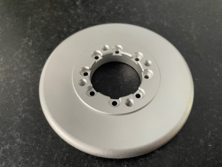
A casting is a near-net shape. It is rarely a finished part. Sealing faces, bearing bores, threaded holes, and datum surfaces usually need machining, and the design has to reserve stock for it. If the casting is modelled at final size with no allowance, the machine shop has nothing to remove.
The useful rule is to machine only what the function demands. Every machined surface adds cost, adds a setup, and adds a place for a fixture error. Bores and sealing faces earn it. Cosmetic surfaces on a non-critical bracket usually do not.
We hold ±0.005 mm (±0.0002 in) on machined features and Ra 0.8–1.6 μm on standard functional faces, with Ra 0.2–0.8 μm available when a surface needs it. Those numbers apply to the machined feature, not to the as-cast surface, and the drawing should say which is which.
Cast-then-machine also beats machining from solid on larger parts. A housing that would need a 4,000 mm machine travel and hours of roughing can be cast close to shape and finished in a fraction of the time. The casting carries the geometry; the CNC carries the tolerance.
- 1Reserve stock0.3–0.8 mm on faces that will be machined.
- 2Datum firstPick the machining datum from the casting, not from thin air.
- 3Separate calloutsMark as-cast and machined tolerances on the drawing.
Standard Die Casting vs Design Focused ODM
Where the two models differ in practice.
| Item | Standard die casting | Design focused ODM |
|---|---|---|
| Who owns DFM | Customer's design team | Shared with the die caster |
| When DFM happens | After the PO, sometimes after tooling | Before the tool is cut |
| Draft and radii | Fixed by the customer model | Reviewed and adjusted |
| Gate and overflow layout | Set on the shop floor | Set in simulation |
| First sample outcome | Iteration likely | Fewer loops, if the inputs are honest |
| Change cost | Tool correction | Model edit |
| Best fit | Frozen, proven geometry | New parts, tight timelines |
When This Approach Fits
If the geometry is new and the tool has not been cut, bring us in at the model stage: the DFM work costs you nothing and removes the expensive kind of mistake. If the part is already in production and the tool is proven, a standard casting supplier is the cheaper route and we will tell you so.
Questions Engineers Ask Before Tooling
How early should the die caster see the model?
As soon as there is a solid model with the main walls and ribs, even if the fine features are still moving. The early review catches wall thickness and draft, which are the two things that are expensive to change later.
Waiting for a fully detailed drawing usually means the design has already been frozen around assumptions that may not hold in the cavity.
Can a design focused ODM partner work from a 2D drawing only?
It is possible for simple parts, but the review is weaker. Wall thickness, draft and corner radii are hard to verify from views alone, and simulation needs a solid.
If only a drawing exists, we build the model first and confirm it against the drawing before the DFM report goes out.
How many iterations should we expect before the first good sample?
With a clean DFM cycle and a simulated gate layout, one sample round is typical for the geometry to be correct. Cosmetic tuning may need a second round on textured or visible surfaces.
The number depends on how much of the geometry is new. A part based on a proven family casts faster than a first-of-its-kind housing.
Does a smaller wall thickness always mean a lighter part?
No. Below the filling limit for the alloy and flow length, the cavity will not fill and the shot needs more pressure, which raises flash and tool wear. There is a floor set by the process, not by the CAD model.
Removing material from a thick section is usually the better move: it cuts weight, cuts cycle time, and removes the hot spot at the same time.
What should be on the drawing for a cast-then-machined part?
Mark which surfaces are as-cast and which are machined, and give the machining allowance on the casting model. State the datum that the machine shop will use.
Datums taken from a rough cast surface will move with every shot. Pick a machined face or a cast boss that is stable.
Can tooling and finishing stay with one supplier?
They can. Casting, machining and finishing under one roof removes the shipping step between operations and keeps the datum chain intact.
It also means the surface finish callout is handled by the same team that controls the casting skin, which matters on visible parts.
Send the Model, Get the DFM Back
Upload a STEP file and we return a quotation with a free DFM analysis within 12 hours, under NDA if you need one.
12-hour quote100% inspectionNo minimum order
GreatLight Elsewhere
We publish setup notes, tooling trials and inspection data from the factory floor.











