
Design Driven Bulk Rapid Tooling ODM: How a Design File Becomes 10,000 Parts
This page explains what a bulk rapid tooling ODM actually does between your frozen CAD file and a 10,000-part production run, and where that route stops making sense. It is written for design engineers and sourcing managers who have to defend a process choice, not just place a PO. Read it and you can tell whether your part should go through tooling, through machining, or through both in sequence.
In this article
- 1
- 2
- 3
- 4
- 5
- 6
- 7
- 8
What Bulk Rapid Tooling ODM Means in Practice
A bulk rapid tooling ODM does two jobs that are usually split between a design house and a machine shop. The first is reading your design intent before any steel is cut. The second is running the tooling that carries that intent through thousands of parts. When those jobs sit with one supplier, the DFM notes you get back are not suggestions from a vendor who will never see the tool run. They are commitments from the people who will.
The word bulk matters more than rapid. Rapid describes the front end: quoting, DFM, first-article samples, all compressed into days. Bulk describes the back end: a stable process that holds the same dimension on part 1 and part 10,000. A shop that is fast but drifts after 500 cycles has not delivered bulk tooling, no matter what the first article measured.
Design driven is the third term, and it is the one buyers tend to skip. It means the manufacturing partner is allowed to push back on the drawing. A 1.5 mm wall next to a Ø8 mm boss may look fine in CAD and still fill short in a die. A parting line that crosses a cosmetic surface may be legal on the print and ugly on the shelf. An ODM partner raises those points while the fix is still a mouse click, not a welding rod.
So in practice, the scope runs from raw material to finished, inspected parts under one roof: tool design, tool build, sampling, first article inspection, and the production run itself. That is a wider scope than build-to-print machining, and it is narrower than full product design. The boundary sits at your design freeze.
- 1Rapid front endQuote and DFM analysis inside 12 hours, production start inside 24 hours
- 2Bulk back endProcess control that holds dimensions across a 10,000-part run
- 3Design drivenManufacturability feedback raised before design freeze, not after
How the Design Freeze Turns Into a Tooling Plan
Tooling planning starts with a small set of numbers, not a full review. We look at wall thickness spread, draft on every vertical face, gate or fill location, and the datum scheme your inspection will use. Those four items decide most of the cost and most of the late surprises. A 2 mm wall next to a 4 mm rib cools at a different rate, and that difference shows up as sink or warp long before it shows up on a CMM report.
The datum scheme is where design and tooling most often disagree. If your print calls A-B-C datums that only exist after assembly, the tool cannot hold them. We re-map the datums to features the tool actually controls, then confirm the stack-up still closes. If it does not, the fix belongs in your design, not in our fixture.
Draft is the second common friction point. Textured surfaces need more draft than polished ones. Fine bead blasting or a matte texture can need 1.5° to 3° per side on vertical walls; a polished cavity can run with less. Adding draft after the tool is cut means metal is removed from the cavity, which changes the part, not just the tool.
Once those three items are settled, we pick the process route. That route is a cost-versus-volume decision, not a preference. The next section lays out the numbers we use to make it.
- 1Wall thicknessKeep spread within about 2:1 across one part to limit warp
- 2Draft1.5°–3° per side on textured walls; less on polished cavities
- 3DatumsMap to features the tool controls, then re-check stack-up
When Bulk Tooling Beats CNC Machining, and When It Does Not
Below about 200 parts, machined parts are almost always cheaper per unit than molded or cast ones. There is no tool to amortize, no sampling round, no first-article report. If your quantity is 20 aluminum housings for a bench build, machining them from plate is the right answer, and any supplier who pushes you toward tooling at that volume is selling the wrong service.
Tooling starts to win when the per-part cycle time and material removal cost exceed the tool amortization. That crossover sits somewhere between 200 and 1,000 parts for most mid-size enclosures, and it moves with part geometry. A part with deep pockets and thin ribs is expensive to machine and cheap to mold. A part with a single tight bore and a flat face is the opposite.
Some features never belong in a mold. A ±0.005 mm bearing bore, a sealing surface that has to hold Ra 0.8–1.6 μm, or a thread that must survive repeated assembly may need secondary machining after molding. That is normal, and it should be planned in the tool design, not discovered at the assembly bench.
The other boundary is cosmetic class. If the visible surface has to be flawless and the part is large, tooling cost rises fast because surface finish in the cavity is hand work. For a few hundred parts, machining and polishing a billet part can beat building a cavity that needs the same polish.
- 1Under ~200 partsCNC from billet, no tooling spend
- 2200–1,000 partsCrossover zone, decide per part geometry
- 3Tight boresPlan secondary machining into the tool design
Why Certifications Change the Tooling Plan
Process control is the thing a certificate actually documents. IATF 16949:2016 requires documented defect prevention and traceability across the production run. ISO 13485:2016 adds design and process validation records for medical hardware. ISO 9001:2015 is the baseline quality system. ISO 27001:2022 covers how your CAD files and drawings are stored and who can open them.
For an engineer, the practical effect is what happens after a bad part appears. In an audited system, the non-conformance has a record, a containment action, and a root-cause step. In an unaudited shop, the same bad part often becomes a phone call and a rework batch. The difference matters most when the parts go into a vehicle, a pump, or a device that a regulator will inspect.
Data handling is the quieter half. Drawings and CAD files carry your product's geometry, and for unreleased products that geometry is the asset. ISO 27001:2022 means access control, retention rules, and an auditable trail for who opened which file. An NDA covers intent; access control covers execution. You want both.
None of this replaces first article inspection. Certification says the process is controlled. Inspection says this batch of parts is correct. A supplier needs both, and so does your incoming inspection plan.
- 1IATF 16949:2016Automotive hardware, defect prevention, traceability
- 2ISO 13485:2016Medical devices, validation and records
- 3ISO 27001:2022Drawing and CAD file access control
What Has to Be Under One Roof
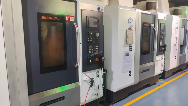
Tooling does not live alone. A cavity insert that needs a shutoff machined to ±0.005 mm, a core pin that needs grinding, a hardened slide that needs wire EDM: these are separate operations, and moving parts between shops adds days and tolerance stack-up. GreatLight runs 127 high-precision CNC machines across 3 wholly-owned plants, in a 7,600 m² facility in Dongguan, China, with a second site in Singapore.
The machine mix matters for the parts that come out of the tool. There are 16 simultaneous 5-axis machining centers, 12 four-axis mills, 27 three-axis machines and 16 mill-turn centers. Maximum processing size is 4,000 mm, with travels from 500 × 310 × 200 mm up to 4,000 × 400 × 150 mm and a Ø400 mm rotary table. That range covers both mold inserts and the fixtures that hold parts for secondary operations.
Post-processing sits in the same building. Anodizing in clear, color, hardcoat and conductive; electroless nickel, zinc, silver and gold plating; powder coating and black oxide; bead blasting, tumbling, brushing and polishing. Laser marking holds a minimum character height of 1.5 mm. When the cosmetic spec changes, the change does not require a new supplier qualification.
Materials run from aluminium 6061, 6061-T6, 2024, 5052, 5083, 6063, 6082, 7075 and ADC12, through stainless 303, 304, 316, 316L, 420, 430, 431, 440C and 17-4PH, to tool steel, copper alloys, titanium TA1, TA2, TC4, Inconel and magnesium AZ31B or AZ91D. The alloy list is what makes the tool design decision concrete rather than theoretical.
- 1127 CNC machines16 five-axis, 12 four-axis, 27 three-axis, 16 mill-turn
- 24,000 mm max sizeCovers mold inserts, frames and secondary fixtures
- 3Finishing in-houseAnodizing, plating, powder coat, laser marking
Where Bulk Tooling Programs Actually Go Wrong
Most failures trace back to a design revision that arrives after the tool is cut. A boss moves 2 mm, a wall thins, a snap fits tighter. Each change means welding or re-cutting cavity steel, and welded steel behaves differently from the original block. The fix is boring: freeze the design, then change it on purpose, not by drift.
The second failure is a tolerance that the process cannot hold on day one and will not hold on day 5,000 either. A molded part that needs ±0.005 mm across a long dimension will fight you for the whole run. Keep the tight tolerances on machined features and leave molded dimensions at realistic process capability.
The third is inspection planning. If the print defines datums that no fixture can reach, the first article becomes an argument about measurement rather than a check of the part. Bring your inspection method into the DFM conversation, especially for parts with freeform surfaces.
The fourth is volume forecasting. A tool built for 5,000 parts and run to 30,000 will wear, flash and drift. Tell the tool designer the real expected volume, including the optimistic case, so the steel and cooling layout match it.
- 1Late design changeWelded or re-cut cavity steel behaves differently
- 2Unrealistic toleranceKeep ±0.005 mm on machined features, not molded spans
- 3Volume mismatchDeclare the optimistic volume, not just the first PO
From Frozen CAD to 10,000 Parts in 5 Steps
Typical sequence on a design-driven bulk tooling program.
- 1Step 1 – Upload and DFMSend STEP or native CAD plus the 2D print with datums and tolerances. You get a quotation and a free DFM analysis within 12 hours, listing wall thickness issues, draft conflicts and datum problems.
- 2Step 2 – Design freeze and tool layoutResolve the DFM points in your CAD, then freeze the revision. We lay out the cavity, gate or fill location, ejection and the datum scheme the tool will control. Production can start within 24 hours of the freeze.
- 3Step 3 – Tool build and samplingCut the cavity and core, fit the tool, then run first-article samples. Measure every print dimension and compare against ±0.005 mm where the print calls for it. Surface finish targets are checked against Ra 0.8–1.6 μm or finer as specified.
- 4Step 4 – First article and correctionReview the first-article report with your engineering team. Correction here means adjusting the tool while it is still on the bench. After the run starts, changes cost far more.
- 5Step 5 – Production run and inspectionRun the volume with in-process monitoring. Every shipment gets 100% inspection before it leaves, with raw material check, in-process checks and final inspection. Inspection reports are available on request.
Which Route Fits Which Volume
Rough windows only. Real crossover depends on part size, wall thickness and cosmetic class.
| Volume | Route | Lead time | Best fit |
|---|---|---|---|
| 1–20 parts | CNC machining from billet or plate | 3–5 days | Fit and function checks, no tooling spend |
| 20–200 parts | Vacuum casting or soft tooling | Days to 2 weeks | Design verification, bridge builds |
| 200–5,000 parts | Aluminum or soft steel tooling | Weeks, not months | Bridge to mass production, modest cosmetic needs |
| 5,000–10,000+ parts | Hardened production tooling | Longer front end, stable run | Dimensional and cosmetic repeatability at volume |
| Any volume, tight tolerance | 5-axis CNC, ±0.005 mm | 3–5 days | Features a molded part cannot hold |
The Honest Split
If you need fewer than 200 parts and the geometry is machinable, buy CNC parts and skip tooling. If you are past roughly 1,000 parts with a stable design and a cosmetic requirement, a design-driven bulk rapid tooling ODM will beat machining on unit cost and repeatability. Between those two numbers, decide per part, not per policy.
Questions Engineers Ask Next
How do you decide between aluminum tooling and hardened steel tooling?
Aluminum and soft steel tooling make sense for bridge volumes, usually a few hundred to a few thousand parts, where the design may still move. Cycle life is lower and wear appears earlier, so they are a bad fit for a long production run.
Hardened tooling costs more up front and takes longer to build, but it holds dimensions and surface finish across high volumes. If your forecast includes a second or third production year, the hardened route is usually the cheaper one over the whole program.
Can you machine features into the part after molding?
Yes, and it is common. Tight bores, sealing faces and precision threads are often produced by CNC after the molded or cast part cools and stabilizes. Those operations run on the same 5-axis and mill-turn equipment, to ±0.005 mm where the print requires it.
The important part is planning. If secondary machining is expected, the tool design has to leave stock and a locating feature for the fixture. Adding that after the tool is built means reworking the tool.
What happens if the first article is out of tolerance?
The tool is still on the bench, so correction is a tool change, not a production change. We adjust the cavity, the gate, the cooling or the ejection, then re-sample and re-measure against the print.
This is why the first article review matters more than the quote. A supplier that measures loosely at this stage passes the problem to your assembly line, where the fix costs ten times more.
Do you sign an NDA before I share CAD files?
Yes. An NDA is available on request, and uploads are treated as secure and confidential. The facility also holds ISO 27001:2022 for information security, which governs file access and retention.
For unreleased products we recommend the NDA plus a named point of contact on both sides, so drawing distribution stays inside a known list.
What is the smallest and largest part you can run?
Machining travels range from 500 × 310 × 200 mm up to 4,000 × 400 × 150 mm, with a Ø400 mm rotary table, so both mold inserts and large frames fit. Maximum processing size is 4,000 mm.
For tooling, the practical limit is usually the press or machine that will run the tool, not our cutting capacity. Share the intended machine and we can confirm fit during DFM.
How fast can a program start?
Quotation and free DFM analysis come back within 12 hours. Once the design is frozen and the tooling plan is agreed, production can start within 24 hours, and machined parts ship in 3–5 days.
Tool build itself follows the tooling schedule, which depends on cavity complexity and surface finish requirements. We confirm those dates in writing before the tool is cut.
Send the Drawing, Get the DFM Notes
Upload your CAD and print. You get a quotation and a free DFM analysis within 12 hours, plus a straight answer on whether your volume belongs in tooling or in CNC.
12-hour quoteNo MOQIATF 16949100% inspection
More Process Notes
We publish setup notes, tooling trials and inspection data from the factory floor.











