
Choosing a Metal 3D Printing Maker: Process Limits and 5 Checks
Laser powder bed fusion builds geometry that milling cannot reach, but the as-built part is rarely the finished part. This page explains how the process works, where it stops working, and how to judge a metal 3d printing maker before you send a drawing.
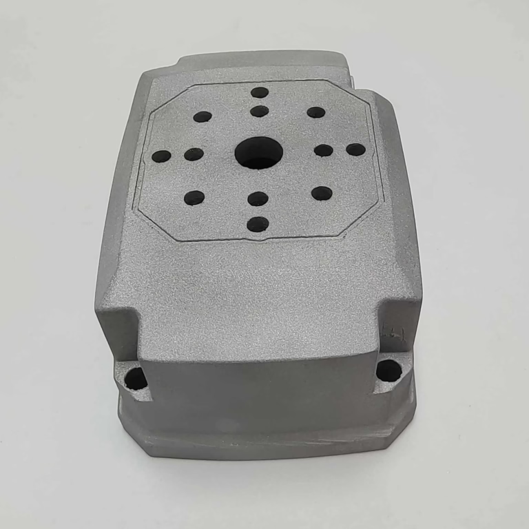
What a Metal 3D Printing Maker Actually Controls
Metal 3D printing for engineering parts means laser powder bed fusion. A 20–60 μm layer of gas-atomized powder is spread across a build plate, a fiber laser melts the cross-section, and the plate drops by one layer. Repeat a few thousand times and you have a part. The two names you will see are SLM (selective laser melting) and DMLS (direct metal laser sintering). Both fully melt the powder. The difference is marketing history, not physics.
The variables that decide whether your part is good are not the laser brand. They are layer thickness, laser power and scan speed, hatch spacing, and the support strategy. A 30 μm layer thickness with tight hatch spacing gives a dense part at a slower build rate. A 60 μm layer builds faster and leaves a rougher downward-facing surface. Every maker trades these against each other, and you should ask which side of that trade your part landed on.
Support removal is where drawings quietly break. Supports are welded to the part by the same laser that built it. On internal channels and lattice struts, they have to be cut out by hand or with a wire EDM pass. If a maker quotes without asking about support access, the quote is a guess.
Dimensional reality: as-built laser powder bed fusion holds roughly ±0.1 mm on small features under good conditions, and worse on long unsupported spans. That is not a finished tolerance. It is a starting point for machining, and any maker who promises ±0.005 mm straight off the printer is describing a different process than the one they run.
- 1Layer thickness20–60 μm; thinner layers mean finer detail and slower builds.
- 2Build orientationDecides support volume, surface finish, and anisotropic strength.
- 3Support strategyBlock, tooth, or lattice supports change how much hand work follows.
- 4Residual stressThick sections can warp or crack during cooling; stress relief is often required.
Where Additive Stops and Subtractive Takes Over
Most production metal parts that come off a printer are not finished parts. Build plate removal, support cutting, stress relief, and then machining of the critical interfaces. A bore that has to take a bearing, a face that has to seal, a thread that has to hold torque: none of these come off the printer at specification.
This is why the useful question is not "can you print this" but "what happens after you print this." A shop with 5-axis machining centers on the same floor can cut the printed blank back to ±0.005 mm on the datums and sealing faces without a second supplier, a second shipping step, and a second set of setup fixtures.
Consider a conformal-cooled injection mold insert. The cooling channels follow the cavity curve, which no drill can reach. The print gives you the channels. Then the cavity surface still needs to be milled and polished to Ra 0.2–0.8 μm, and the mounting faces need to be flat. Separate vendors mean the insert travels between them, and each trip adds setup error.
Thin-wall and lattice parts behave differently. If the whole point of printing is a 0.4 mm wall or a 60 percent porous lattice, you cannot machine the outside without destroying the feature. Those parts are usually finished by hand, bead blasting, or a light tumbling pass, and the print itself carries the tolerance. Know which category your part is in before you argue about machining.
One more handoff worth naming: heat treat and finish. Electroless nickel, anodizing, and black oxide all interact with printed surfaces differently than with wrought stock. Porosity that is sealed in a casting can stay open on a printed face and wick plating solution. A maker who controls the finishing step can pick a process that suits the printed surface instead of the default.
- 1Datums and boresMachine after printing; ±0.005 mm is achievable on rigid setups.
- 2Sealing facesUsually need milling and lapping; as-built roughness is too high.
- 3ThreadsCut or form after printing; printed threads are not a production answer.
- 4Cosmetic surfacesPolish, blast, or brush depending on the specified Ra band.
Five Checks Before You Send a Drawing
First, ask what happens to your file. A maker who prints directly from your STEP file may miss wall thickness limits, trapped powder volumes, and unsupported overhangs. DFM feedback inside 12 hours, before the quote, tells you the engineering desk is real.
Second, ask how the part is measured. Printed parts need more than a caliper. CMM, 3D scanning, and optical measurement can map a freeform surface that no touch probe can follow. If inspection is only "visual check before packing," you are buying a prototype, not a production part.
Third, ask about material traceability. 17-4PH, Ti-6Al-4V (TC4), Inconel, and aluminum powders all have different oxygen pickup behavior, and powder reuse cycles change the result. A maker who cannot tell you the powder lot and the reuse count cannot explain a mechanical property shift three months later.
Fourth, ask about single-point accountability. If the printer, the machine shop, and the finisher are three companies, nobody owns the final dimension. One purchase order, one inspection report, one party to call when a bore comes in oversize.
Fifth, ask about confidentiality. Drawings for aerospace brackets and medical instruments carry real IP. Secure upload handling and an NDA on request are table stakes, not a favor.
None of these checks require a plant visit. They require a maker who answers in specifics rather than adjectives. If the reply to "what tolerance do you hold after machining" is a number and a measurement method, keep talking. If it is a sentence about quality, move on.
- 1DFM before quoteWall thickness, powder escape, support access flagged in writing.
- 2Measured, not eyeballedCMM, 3D scanning, optical inspection with reports on request.
- 3Powder lot and reuseAsk for the lot number and the reuse count for the build.
- 4One order, one ownerPrinting, machining, and finishing under the same roof.
When Printing Beats Machining, and When It Does Not
Rough guide for metal parts between 20 mm and 400 mm
| Part feature | Printed blank | Machined from solid |
|---|---|---|
| Internal conformal channels | Yes, no drill can reach them | Not possible |
| Lattice or porous structure | Yes, designed into the build | Not practical |
| Simple prismatic block | Possible but costly | Faster and cheaper |
| Tight bore or bearing seat | Print then machine | Machine directly |
| Sealing face, Ra 0.8–1.6 μm | Print then mill and lap | Mill directly |
| Thin 0.4 mm wall | Yes, print carries tolerance | Chatter risk, hard to hold |
| High-volume simple part | Rarely economical | Die casting or machining |
| One-off complex bracket | Strong fit | Slow, high material waste |
The Short Version
If your part has internal channels, lattices, or organic load paths, print it and machine the critical interfaces afterwards. If it is a simple prismatic part with a few tight bores, machine it from solid and skip the print entirely. A maker who tells you which of those two you have is worth more than one who quotes both.
Questions Engineers Ask
What tolerance can I expect on an as-built printed surface?
Laser powder bed fusion holds roughly ±0.1 mm on small features under good conditions, and looser on long unsupported spans. Downward-facing surfaces are rougher than upward-facing ones, often Ra 8–12 μm before any finishing.
Treat that as a blank tolerance. Anything functional gets machined after printing, where ±0.005 mm is realistic on rigid setups with correct datums.
Which metals can be printed?
Common choices are 17-4PH stainless, 316L, Ti-6Al-4V (TC4), Inconel, and aluminum alloys such as AlSi10Mg. Each has different printability: aluminum is light and conductive but harder to weld into dense parts, while titanium needs an inert atmosphere and careful support design.
Tell us the service conditions, not just the alloy name. Temperature, corrosion exposure, and load direction all narrow the list.
How long does a print and machine cycle take?
Build time scales with part height, not part count. A short build can finish in hours; a 200 mm tall job runs overnight or longer. Add support removal, stress relief, and machining on top.
GreatLight can start production within 24 hours of an approved order, with parts shipping in 3–5 days for typical jobs.
Is there a minimum order quantity?
No. We run from a single prototype to runs of 10,000+ parts. For printed parts, the economics favor small batches anyway, because the tooling cost is zero and the per-part cost is driven by machine time.
How do you handle my drawings and IP?
Uploads are secure and confidential. An NDA is available on request before you send files, and it covers the drawings, the models, and any process information we generate from them.
Can you combine printing with casting or sheet metal in one order?
Yes. If a subassembly mixes a printed bracket with a die-cast housing and a sheet metal cover, we can produce all three and inspect the assembly together, which removes the tolerance stack you would get from three separate suppliers.
Send the Drawing, Get a Real Answer
Upload your STEP file and get a quote with DFM feedback inside 12 hours, from a shop that prints, machines, and inspects on the same floor.
12-hour quote100% inspection before shipmentNo minimum order quantity
Follow GreatLight
We publish setup notes, tooling trials and inspection data from the factory floor.











