
Low Volume CNC CO Detector Housing: How Process Choice Shapes Sensor Performance
A CO detector housing is a sealed mechanical reference, not a box. This page explains how wall thickness, sealing geometry, insert strategy and finish interact in low volume CNC co detector housing work, and when another process fits better.
In this article
- 1
- 2
- 3
- 4
- 5
- 6
- 7
Why a CO Detector Housing Is a Mechanical Reference, Not a Box
A carbon monoxide sensor responds to gas concentration, but the number on the display depends on the air reaching it. The housing sets that path. Vent slots define diffusion resistance. Internal volume defines how fast the sample mixes. Wall thickness defines how much heat the electronics must push through before the thermistor or the sensor heater reaches equilibrium. Change any one of those and the calibration curve shifts.
In low volume cnc co detector housing production, the housing is usually the first part of the assembly that has to change when the sensor or the PCB is revised. That is the practical reason CNC suits this stage. A mold locks the geometry. A machined housing lets you move a vent, deepen a groove or add a boss between revisions without scrapping tooling.
There is a second reason. Sensor cells are often bought in small batches from specialist suppliers, and the electronics may be built 50 or 200 units at a time. Injection molding needs tens of thousands of shots to amortize a mold, so the unit cost at 200 pieces is dominated by tooling, not by the part. Machining spreads no tooling across the run.
The trade-off is real. Machining costs more per part than molding at high volume, and it imposes design rules that molding does not. Thin free-standing walls chatter. Deep narrow pockets need long tools that deflect. Sharp internal corners cannot be milled. If you know those limits before you finalize the model, the first article usually passes. If you learn them after, you pay for a second setup.
- 1Housing sets the gas pathVent area and internal volume define sensor response time.
- 2Machining survives revisionsGeometry changes need no new tooling between builds.
- 3Mold cost dominates small runsAt 200 units, tooling amortization outweighs per-part savings.
Wall Thickness, Sealing Grooves and the Tolerances That Actually Matter
Most CO detector housings we machine are aluminum or ABS. Aluminum 6061-T6 gives stiffness, good thermal conduction and a clean anodized finish. ABS, PC or POM suit designs where the housing must insulate the electronics or where the antenna or sensor window has to stay radio-transparent. Stainless 304 or 316L appears when the unit goes into a boiler room, a parking structure or a marine environment.
Wall thickness is the first decision. For machined aluminum, 1.5 mm to 2.0 mm is comfortable on a housing of 80–120 mm across. Below 1.0 mm the wall becomes a tuning fork. A 0.8 mm wall on a 100 mm panel will sing at spindle speeds above roughly 8,000 rpm, and the finish shows it. If the design needs a thin cosmetic wall, keep the load-bearing ribs at 2.0 mm and let the thin section span only short distances between supports.
Sealing is where the tolerance budget concentrates. A face seal groove for an O-ring typically runs 1.5–2.5 mm wide and 1.0–1.8 mm deep depending on cord diameter, held to ±0.05 mm on depth. A gasket land only needs flatness: 0.05 mm over the full sealing face is a workable target, and 0.02 mm is achievable on a rigid part with a single fixturing. The general tolerance for the housing is ±0.005 mm where it matters, but applying that number to every dimension raises cost with no benefit.
Vent geometry deserves its own note. Slot width below 0.8 mm is hard to mill cleanly at depth, and burrs there directly block airflow. We usually recommend slots of 1.0–1.5 mm width with a 2:1 depth-to-width limit, then deburr and verify with a pin gauge. If the certification body requires a specific free area, tell us the number and we will hold it as a controlled dimension.
- 1Aluminum 6061-T6Stiff, anodizable, good heat path. Default for wall-mount units.
- 2ABS / PC / POMInsulating, light, no corrosion risk. Good for battery units.
- 3Stainless 304 / 316LBoiler rooms, parking garages, marine and wash-down areas.
Inserts, Threads and Conductive Paths in Small Runs
Threaded inserts are a common failure point in low volume work because the design was written for molding. A brass heat-set insert needs a molded boss with a specific wall section. In a machined housing you have two better options. Cut the thread directly into the aluminum with a forming tap, which gives a stronger thread than a cut tap in 6061, or press-fit a knurled insert into a bored hole held to ±0.02 mm. Both avoid insert-mold tooling and both can be done in the same setup as the pocket.
Conductive paths are the other feature that separates a CO detector housing from a generic enclosure. Some designs use a conductive gasket or a metallized contact to tie the housing to circuit ground. If that path is machined, the contact face needs to be flat and free of anodize. Masking a single face during anodizing is normal, but the mask line moves slightly, so keep at least 1.5 mm between the masked area and any cosmetic surface.
For units that must survive a drop test or a vibration profile, the housing usually carries the load through the mounting bosses, not the walls. Bosses of 4–6 mm diameter with a 2.5 mm wall around the thread survive most profiles. A boss tied to a side wall with a short rib costs nothing at the design stage and removes a lot of flex.
Board standoffs need the same treatment. A standoff machined to a flat height within 0.05 mm keeps the PCB from twisting, which matters when a pressure or humidity sensor sits on that board. Twisting changes the reading more than the housing tolerance does.
- 1Formed threads in aluminumStronger than cut threads, no insert, no additional setup.
- 2Press-fit knurled insertsBore held to ±0.02 mm; check pull-out on the first article.
- 3Masked anodize for groundKeep 1.5 mm between mask line and cosmetic faces.
When Low Volume CNC Is the Right Call, and When It Is Not
Low volume CNC wins when the count is small, the geometry is still moving, or the material is not moldable. A run of 1 to 500 units with two or three design revisions inside a year is the classic case. So is a stainless housing, because stainless is expensive and slow to die-cast and there is no practical injection-molding route for a metal part.
It also wins when the sealing surface has to be machined after any forming step. A die-cast or sheet-metal housing often needs a secondary face-milling operation on the gasket land. If that operation is required anyway, machining the whole housing from bar or plate removes one process step and one set of handling damage.
Sheet metal becomes attractive above roughly 500 units when the housing is a simple folded box with no deep pockets, no sealing groove and no tight bore. The tooling is a punch and a brake program, the cost is low, and the lead time is short. What you lose is flatness on large faces and any hope of holding a bore to ±0.005 mm without a secondary machining step.
3D printing fits the earliest stage, when you need to check fit and connector clearance in your hand. It does not fit a housing that has to pass a thermal or flammability test, and it does not give a gas-tight groove. Use it for the ergonomic check, then move to machined or molded parts for the units that leave the building.
Die casting takes over somewhere around 2,000 to 5,000 units when the geometry has stopped changing and the wall sections are uniform. Below that, the mold cost sits in every unit's price. Machining has no such penalty, which is why it stays competitive far longer than most teams expect.
- 1Choose CNC1–500 units, moving geometry, metal bodies, machined sealing faces.
- 2Choose sheet metal500+ units, simple folded enclosure, no sealing groove needed.
- 3Choose 3D printingFit checks only. Not for certification or gas sealing.
- 4Choose die casting2,000+ units, frozen geometry, uniform wall sections.
How a Housing Gets Made: Setup, Fixturing and First Article
The first operation is almost always the back face or a datum surface. We hold the blank in soft jaws machined to the part profile, which supports the thin walls and keeps the part from lifting. A housing with an open cavity is far easier to hold on a solid block than a housing that has already been hollowed out, so the sequence matters as much as the machine.
The cavity comes next, usually on a 3-axis mill for a simple shell. When the part has angled faces, vent slots on two or three planes, or a sealing groove that has to stay concentric with a bore, a 5-axis setup cuts the number of fixtures. Each additional fixture adds a small position error and a handling risk, and both show up on the sealing face.
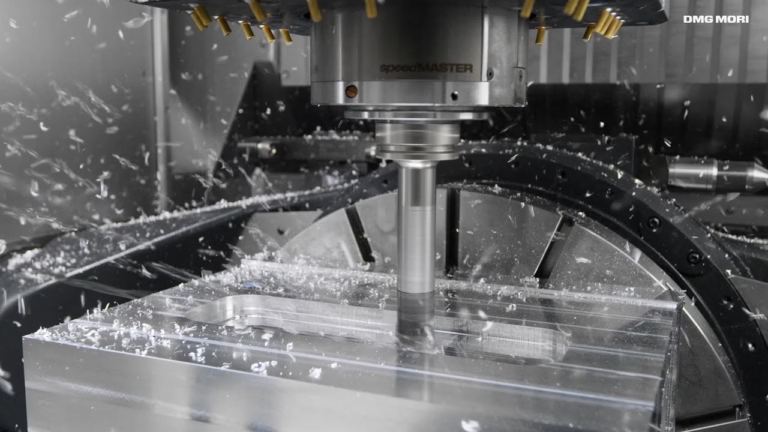
Vent slots are cut with small end mills at conservative feed rates. A 1.0 mm slot in aluminum runs well at 12,000–18,000 rpm with light radial engagement. Pushing the feed to save cycle time is how slots come out with burrs that later block airflow. We deburr by hand or by tumbling, then check slot width with a pin gauge on the first article.
Threads and inserts go in after the cavity, before finishing, so that any deburring happens on bare metal. If the part is anodized, masking is applied at this point. Then the first article goes to inspection: bore diameters, groove depth, flatness on the gasket land, slot width and thread depth. We inspect 100% before shipment, and reports are available on request.
The whole sequence usually runs in 3–5 days once the model and finish are frozen, with quotation and a free DFM analysis back within 12 hours and production start inside 24 hours.
- 1Fixture on solid stock firstMachined soft jaws support thin walls during the first op.
- 2Consolidate with 5-axisFewer setups means less position error on sealing faces.
- 3Deburr before finishingVent slots are the highest-risk feature for airflow blockage.
Why Certification and Traceability Change the Housing Design
A CO detector that carries a safety mark is not just a sensor plus a box. The certification body will ask how the enclosure behaves in the temperature and humidity range it claims, and how you control the parts that make it. That is where documentation enters the housing specification, not as paperwork for its own sake but as evidence that the 200 units you ship next month match the 200 you shipped last month.
GreatLight holds ISO 9001:2015, IATF 16949:2016, ISO 13485:2016 and ISO 27001:2022. For a CO detector housing, ISO 9001 covers the general quality system; ISO 13485 matters when the detector is a medical accessory; IATF 16949 matters for automotive or vehicle-cabin variants; ISO 27001 covers how customer drawings and files are handled. A supplier without a documented system can still cut metal well, but cannot give you the records a certification audit will ask for.
Traceability is the practical part. Material certificates, in-process measurements and final inspection records let you answer a question months later about one serial number. If your customer is an OEM, that answer is often the difference between a closed issue and a recall.
One more point that is easy to miss. Confidentiality is part of traceability when the housing is proprietary. Uploads are treated as confidential and we sign an NDA on request, which matters when the housing geometry itself is the competitive advantage.
- 1ISO 9001:2015General quality system and documented inspection flow.
- 2ISO 13485:2016Medical accessory versions of the detector.
- 3IATF 16949:2016Automotive and vehicle-cabin variants.
- 4ISO 27001:2022Handling of customer drawings and files.
Process Fit by Quantity, Geometry and Sealing Need
Read across to find the case that matches your build.
| Case | Best process | Why it fits | Watch out for |
|---|---|---|---|
| 1–50 units, geometry still moving | Low volume CNC | No tooling to scrap when the model changes | Per-part cost is higher than molding |
| 50–500 units, aluminum body | Low volume CNC | Anodize and machined groove in one flow | Fixture design drives the finish |
| 500+ units, folded box, no groove | Sheet metal | Low punch and brake cost, short lead time | Flatness on large faces |
| Fit check before tooling | 3D printing | Fast geometry in hand | No gas seal, no thermal rating |
| 2,000+ units, frozen design | Die casting | Low unit cost at volume | Mold cost and long first article |
| Stainless or titanium body | Low volume CNC | No practical casting or molding route | Tool wear raises cutting time |
The Short Version
If your CO detector housing is under about 500 units, still changing, or made of metal, machine it: no tooling to scrap, sealing faces cut in the same setup, and revisions cost nothing but a new model. If the design is frozen, the count is above 2,000 and the walls are uniform, move to die casting and keep CNC for the sealing face only.
Common Questions on Low Volume CNC CO Detector Housings
What wall thickness should a machined CO detector housing use?
For aluminum, 1.5–2.0 mm on a housing of 80–120 mm across is comfortable. Below 1.0 mm the wall vibrates during cutting, and the chatter shows in the surface finish and in the groove depth.
If the design calls for a thin cosmetic panel, keep the ribs and bosses at 2.0 mm and limit how far the thin section spans between supports.
How tight does the O-ring groove really need to be?
Groove depth is the critical dimension, typically held to ±0.05 mm, because it sets the squeeze on the cord. Groove width can be looser, often +0.1/–0 mm.
The surrounding face matters too. Flatness of 0.05 mm over the full sealing face is a realistic target for a rigid machined part; 0.02 mm is achievable with a single fixturing.
Can you machine the housing and leave the sealing face unfinished?
Yes, and it is often the right choice. A gasket land that will be covered does not need a cosmetic finish, and skipping anodize there saves masking work.
What it does need is flatness and freedom from burrs. We define the sealing face as a controlled dimension on the drawing and inspect it on the first article.
When should we switch from CNC to die casting?
When the geometry has stopped changing and the annual volume is above roughly 2,000 to 5,000 units with uniform wall sections.
Below that number, the mold cost sits inside every unit price. Keep the sealing face as a secondary machining operation so the critical geometry stays under CNC control.
How do you handle the vent slots so airflow is not blocked?
Slot width of 1.0–1.5 mm with a depth-to-width limit of about 2:1 mills cleanly in aluminum. Anything narrower than 0.8 mm at depth is where burrs form.
We deburr after milling and verify slot width with a pin gauge on the first article. If a certification body specifies a free area, we hold that as a controlled dimension.
What documentation comes with the parts?
Raw material certificates, in-process monitoring records and a final inspection report are available on request, and every part is inspected before shipment.
For medical or automotive variants, the quality system behind those records is ISO 13485:2016 and IATF 16949:2016 respectively.
Send the Model and Get a DFM Review
Upload the housing model and we will return a quotation with a free DFM analysis within 12 hours, covering wall thickness, groove depth, vent slots and finish.
12-hour quoteNo MOQ±0.005 mm100% inspection
More From the Shop Floor
We publish setup notes, tooling trials and inspection data from the factory floor.











