Research was carried out on the processing of a certain large thin plate workpiece, and a device suitable for processing the workpiece was designed and manufactured. The device can enable the operator to quickly clamp the workpiece, improve efficiency and reduce processing errors. A high-precision CNC probe is used to detect large clamped thin plate parts, extract the depth dimensions of different areas, and obtain the true clamping state of the parts. VB6.0 computer software is used to compile a CNC conversion program to process. the CNC program and standard CNC The processing depth of the program is corrected according to the clamping situation, thereby reducing the impact of clamping errors on the processing quality of parts. Through a large number of process tests and improvement works, we have discovered the most reasonable cutting parameters for processing this part, which can improve productivity and reduce production costs while the durability of the tool is high, and solve the processing and quality control problems of this type of thin plate parts problem.
1 Preface
Thin plate parts are commonly used in aerospace industry products, military products and medical equipment. Their structures are not complex and the precision requirements are not too high. However, due to low rigidity, they are prone to deformation during the tightening process and under tightening. the action of cutting forces, which leads to out-of-tolerance dimensions and milling of parts. In addition, the processing efficiency is low and the processes are numerous. In particular, the fitter takes a long time to level the parts. easy to rework.
In recent years, with the development of computer software and hardware, computers have been combined with finite element method, neural network, genetic algorithm and optimization theory to comprehensively apply to technology. The analysis of deformation in the processing of cutting parts, which can quickly, accurately and reasonably determine the cutting characteristics. The treatment process parameters, to a certain extent, solve the problem of empirical determination of the process parameters.[1]. Through research on processing of thin plate parts, we hope to find a universal processing method which can promote the development of cutting processing technologies for thin plate parts, ensure the processing quality, shorten the preparation time production and processing cycle, reduce production costs and improve productivity.
2 Problems Existing in CNC Milling of Thin Plate Parts
Thin plate parts have simple structure, large volume, low relative rigidity and poor processing technology. Under the action of cutting force, clamping force, cutting chatter and other factors, processing deformation is likely to occur, and it is difficult to control the processing accuracy and improve the processing accuracy. effectiveness of the treatment. Problems of deformation and processing efficiency have become important constraints for processing thin-walled parts.[2,3]。
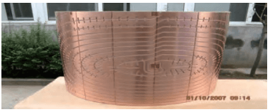
Figure 1 shows a copper plate with a length of 1500 mm, a width of 700 mm and a thickness of 4 mm. A series of spiral grooves with a depth of 3mm should be processed on the copper plate. The process layout is: cutting (1500mm × 700mm × 4mm metal plate) → leveling (within 0.8mm) → aging → bonding → processing of bolt holes of pressure plate → leveling (within 0.3mm) → CNC processing → fitter (including sandblasting), surface polishing, etc.) → Bending (bending forming) → Inspection.
Figure 1 Copper plate
When processing this thin plate part, the part will be twisted or deformed, and these deformations are irregular deformations with large randomness. After processing, the parts are seriously deformed and cannot meet the needs.
3 Improvement and optimization of clamping methods for thin plate parts
3.1 Improvement of vacuum suction cups
Based on the design idea of the fixture for large thin plate parts, an original vacuum suction cup was designed (see Figure 2). After the suction cup parts were connected and tightened, the following problems were found: ① When the). the pieces are uneven, it is difficult to move the pieces. The tightening is fluid. ② Affected by the shape of the parts, it is difficult to clamp the parts to the appropriate position. ③When the parts are clamped, the clamping speed is slow, and it sometimes takes a long time for the vacuum pump to reach saturation. In response to the above problems, corresponding improvements have been made to the vacuum suction cup.

Figure 2 Diagram of the suction cup before improvement
The vacuum suction cup originally consisted of a series of small holes, which were countersunk using a milling cutter (see Figure 3), slightly lower than the other surfaces by 0.5 mm. On the one hand, it is difficult to plug the hole. On the other hand, the vacuum suction cup forms a whole during suction, moving from point contact to surface contact. The effect after improvement is obvious. The improved vacuum suction cup is shown in Figure 4 and its clamping part is shown in Figure 5.

Figure 3 Schematic diagram of the improved suction cup

Figure 4 The truly improved vacuum suction cup

Figure 5 Clamping part improved by vacuum suction cup
3.2 Managing irregular tightening
Since the whole thin plate is uneven and irregular, the idea of finite elements is used to divide it into several parts. As shown in Figure 6, the entire board is divided into countless small pieces. For each small piece, the smaller the division, the higher the flatness.

Figure 6 Flat Plate Segmentation Diagram
3.3 Detect tightening state
Use the CNC machine tool’s own probe to detect different positions of the workpiece according to processing needs, obtain the true state of the workpiece in the clamping state, and record the detection data.
4 Selection and optimization of cutting tools, cutting fluid and cutting parameters
4.1 Tool selection
According to the structural characteristics and process characteristics of thin plate parts, the number of teeth of the processing tool should not be too high. Generally, 2 to 3 teeth are selected. The geometric parameters of the tool must be selected from a reduction perspective. the cutting force. Tools with large front and rear angles should be selected; the helix angle should be between 30° and 45°, excessive helix angle will increase the axial force, while too small helix angle will increase the difficulty of chip removal. . The final tool used is shown in Figure 7.

Figure 7 Machining tools
4.2 Selection of cutting fluid
During the machining process, various cutting fluids were tested and it was found that the use of kerosene can reduce the generation of burrs and have less impact on fixture.
4.3 Selection and optimization of cutting parameters
High speed milling is used to machine this part. Through experiments, when the rotating speed is limited to about 15,000 rpm, the noise is lower (related to factors such as machine tools) and the tool is not easy to break. When the rotation speed is 15,000 rpm, the feed amount is selected as 0.05 mm/r, which results in a feed rate of 750 mm per minute. The processing depth of some parts of this workpiece is 4mm, and the cutting depth needs to be processed to the depth in one go.
5 Toolpath processing and CNC program conversion and optimization
5.1 Processing the toolpath during programming
High-speed milling requires not only high rotation speed, but also fast tool feed speed. When programming, it is necessary to try to process the program into a program suitable for high-speed milling, and the machine tool should be in a relaxed state during processing, that is, the X axis and Y axis do not auto-activate. -lock, so that the machine tool can move smoothly.
5.2 Conversion and optimization of the CNC program
According to the above idea of dividing the thin plate into countless small pieces, one depth can be used for each small piece during processing. For other small pieces, if the depth changes, local oblique milling can be used, so that the whole. a thin plate can be processed. For example, there are some diagonal transitions, but the depth to surface is much improved. Use a CNC probe to detect the depth of different segmented parts, and use VB6.0 to compile a CNC conversion program for the detection results. The processing flow of the program is shown in Figure 8.

Figure 8 CNC program processing flow
The specific processing method used for this thin plate part is as follows: ① According to the conventional method, fix the part on the vacuum suction cup and try to keep the large surface flat. ②After the parts are clamped, use a CNC probe to measure the split areas of the entire part. ③After all programs are executed, transfer the files generated in the machine tool to the computer as tool compensation files. ④Prepare the workpiece processing program in the computer in advance. ⑤ Start the program compiled with VB6.0, enter the login interface, open the CNC program prepared in advance, and select the data just generated by measurement as the tool compensation file. ⑥Set the location and name where the CNC machining program should be saved after conversion, and then click Finish to generate the CNC machining program. ⑦Use the newly converted CNC machining program for processing.
Randomly select an installed part to measure the installation error and convert it through this program. The converted program is as follows.
%
N3GOG40G49G80
N4M6T2
(D=2.5XD)
N5 GOG90G54 X507.75Y345.786S6500M3
N6G05.1Q1
N7G43H2Z20.0M8
N8 Z3.0
N9G1Z-3.4F50
N10X506.951Y345.801F420
N11X501.454Y345.972
N12 X495.959Y346.216Z-3.5
N13X490.468Y346.534
N14 X484.982Y346.925
N15 X479.502Y347.391
N16X476.124Y347.724
N17G2X473.881Y350.458R2.5
N18 X476.112Y352.699R2.5
N19 G1X472.41Y352.229
N20 X466.96Y351.491
N21 X473.088Y350.28
N22X469.249
N23 X467.329Y350.116
N24X466.96Y351.491
N25 X461.522Y350.666
N26X457.66Y350.0
N27X463.107Y349.235
N28X468.563Y348.546
N29 X474.029Y347.931
N30X476.124Y347.724
N31G2X473.881Y350.458R2.5
N32 X476.112Y352.699R2.5
N33G1X483.342Y353.448
N34 X488.821Y353.928
N35X494.306Y354.323
N36 X499.797Y354.633
N37 X505.543Y354.867Z-3.4
N38G3X508.685Y356.455R4.25
N39 G2X511.392Y358.002R4.25
N40G1X522.0Y358.046
N41G2X525.319Y356.45R4.25
N42G3X528.482Y354.857R4.25
N43G1X532.786Y354.699
N44 X538.278Y354.411
N45X543.765Y354.038
N46 X549.246Y353.58
N47X554.719Y353.036
N48X557.779Y352.683
N49G2X559.976Y349.913R2.5
N50X557.741Y347.711R2.5
N51G1X560.419Y347.979
N52X565.883Y348.599
N53 X571.339Y349.295
N54X576.34Y350.0
N55X571.077Y350.887
N56X565.636Y351.689
N57 X569.11Y350.429
N58 X567.079Y350.23
N59X565.636Y351.689
N60X564.825Y349.661
N61 X560.338Y350.51
N62X565.636Y351.689
N63X560.183Y352.405
N64X557.779Y352.683
N65G2X559.976Y349.913R2.5
N66X557.741Y347.711R2.5
N67G1X554.946Y347.432
N68X549.466Y346.961
N69 X543.981Y346.563
N70X539.165Y346.279
N71G3X532.519Y343.2R10.0
N72G1X526.774Y337.179
N73G2X519.539Y334.082R10.0
N74G1X512.0
N75G2X508.705Y335.648R4.25
N76G3X505.543Y337.211R4.25
N77G1X500.94Y337.355
N78X495.445Y337.599Z-3.5
N79 X489.954Y337.914
N80X484.468Y338.3
N81X478.987Y338.759
N82 X473.513Y339.289
N83 X468.046Y339.892
N84X462.588Y340.568
N85X457.139Y341.317
……
M30
6 Promotion of treatment methods
After the part was processed according to this method, all indicators met the requirements, proving the correctness of the test method and the conclusion. Later, this method was used to complete the processing of other parts (see Figure 9). This part is also a thin plate part. Based on successful experience, the device for processing this part was redesigned (see Figure 10). Using the same processing method, qualified parts have also been produced.

Figure 9 Other parts

Figure 10 Fixing the parts
7Conclusion
Based on high-speed milling technology, this item reduces the clamping deformation and processing deformation of parts through a series of research works and process experiments, effectively controls the deformation and improves the quality and treatment effectiveness. The following main conclusions are drawn.
1) Design and manufacture of an assembly suitable for processing large parts made of thin plates. That is, by designing the vacuum suction cup, changing the number of clamping forces, changing centralized clamping to distributed clamping, avoiding excessive local deformation, reducing clamping deformation, and standardizing deformation of the part, so that the parts can be easily installed. the surface of the workbench or fixture, the workpiece clamping deformation error is smaller, reduced from the original 1mm to about 0.4mm.
2) A CNC probe and a computer processing program are introduced before processing. This program directly deals with the clamping deformation error, theoretically reducing the impact of the clamping error and making the bottom surface of the processed part at a constant depth.
3) Optimize and improve processing parameters and CNC machining programs, and correct tool path. When generating tool paths, the workpiece processing deformation and rebound amount are taken into account in advance. By correcting or compensating the nominal tool path, the deformation rebound error is reduced or eliminated, thereby reducing the impact of processing deformation during processing, thereby improving the processing speed and processing efficiency. production. and save money.
4) Through the above series of works, the processing quality of the parts has been greatly improved, and the milling depth of the original inconsistent bottom surface has been greatly improved. Before the improvements, the machining depth varied from 0.7 to 1.5 mm and, in extreme cases, parts were even milled. After the improvement, the processing depth fluctuation is 0.1-0.15mm, which solves the problem of difficulty in controlling the processing quality of large thin plate parts, greatly improves the efficiency of processing, significantly reduces production costs, saves labor and material resources, and improves the competitiveness of the enterprise.
Daguang focuses on providing solutions such as precision CNC machining services (3-axis, 4-axis, 5-axis machining), CNC milling, 3D printing and rapid prototyping services.


