Metal cutting processes are often accompanied by terrifying. The existence of burrs not only reduces the treatment accuracy and the quality of the room, affects product performance and sometimes even causes accidents. For the problems of burning that occur, people generally use the starting process to solve them. Overflow is a non -productive process.
This article first analyzes the main factors affecting the formation of terrifying final strawberries and discusses the methods and techniques of reducing and controlling the terrifying milling of the entire structural design process in manufacturing and treatment.
1. The main forms of blunders in final milling
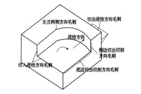
According to the classification system of the cutting cutting movement – Tool Edge Burrs, the terrifying generated during the ending processing process mainly include burrs on both sides of the main edge, blunders on the direction of the Direction side cut, and excavates On the direction of cutting and nourishing and outgoing.
Figure 1 blisters formed by milling
In general, burrs in the cutting direction of the lower edge are large and difficult to eliminate that other terrifies. To this end, this article uses the Burrs Cup management in the base edge as the main research object to carry out research. Depending on the different sizes and shapes of the terrifying in the direction of cutting the intermediate sole of the terrifying grinding (larger, relatively small, can be removed or easily removed) and the terrifying type III are negative lands (like the shows Figure 2).

Figure 2 types of burrs in the cutting direction of the lower edge during grinding
2. The main factors affecting the formation of terrifying
Burr formation is a process of deformation of very complex materials. Various factors such as the characteristics of room materials, geometry, surface treatment, tool geometry, tool cutting trajectory, tool wear, cutting parameters and use of cooling fluid directly affect the formation of Burrs.
Figure 3 is a block diagram of factors affecting the final grinding grounds. Under specific milling conditions, the shape and size of the final milling of the final milling depends on the combined effect of each factor of influence, but different factors have different effects on the formation of terrifying.

Figure 3 Causal control diagram for the formation of the blunder
01. Tool input / output
In general, burrs produced when the tool is screwed in the room is larger than the terrifying products when the tool is screwed in the room.
02. Cut the angle of the plane
The flat cutting angle has a large influence on the formation of burrs in the cutting direction of the lower edge cut. The plane cutting angle is defined as the direction of cutting speed (vector composition of the speed of rotation and the power supply speed) to this point when the cutting edge is turned from the end side of the room, and in the plane passing through the vertical axis of striking striking on the cut edge. The management of the final surface of the part is from the point of vision of the tool to the point of vision of the tool. As shown in Figure 5, ψ is the cutting angle of the plane, and its beach is 0 ° <ψ≤180 °.
The results of the tests show that the height of Burr changes its shape with the change of cutting depth, that is to say with the increase in the cutting depth, the burr goes from type I to burr type II. The minimum grinding depth which produces type II territories is generally called the limit cutting depth, expressed in DCR. Figure 6 shows the effect of the cutting angle of the plane and the cutting depth on the height of the blunder when processing an aluminum alloy.

Figure 6 Flimming and cutting angle and cutting depth
As shown in Figure 6, the larger the cutting angle of the plane, the greater the limited cutting depth; He Burr is also larger. Consequently, the cutting angle of the small plane is conducive to the generation of Type II terrains, because the smaller the ψ ψ ψ ψ ψ the rigidity of the terminal surface is low and the less the terrifying are likely to form .
According to Figure 5, we can see that the amplitude and direction of the power speed will have a certain impact on the amplitude and the direction of the V synthesis speed, and will thus affect the plan of the plan of the plan plan and the formation of the terrace. Consequently, the more the power speed and the outlet angle on the output side are high, the smaller the ψ, the more conducive it is to remove the formation of larger terns (as shown in Figure 7).

Figure 7 Effect of the Directorate of Food on the Flash Formation
03. EOS
During the ending strawberry process, the size of the blunder depends to a large extent on the order of exit of the tip of the tool. As Figure 8 shows: point A is the point on the secondary cut edge, the point C is the point on the main cut edge, and point B is the top of the tip of the tool. Assuming that the tip of the knife is sharp, the arc radius of the tip is not taken into account. If British Columbia leaves the room first and AB leaves the room later, the chips are articulated on the treated surface. Directorate of burrs. If AB first leaves the room, British Columbia leaves the room later, articulated chips on the transition surface and the room is cut, forming a small lower edge to cut the burrs from the cutting direction.
The test shows that: ① The order to leave the tip of the knife which increases the size of the burn in sequence is:
ABC / BAC / ACB / BCA / CAB / CBA. ②The results produced by EOS are the same, except that in the same output sequence, the plastic material is larger than the size of the blunder generated by the breaking material.
The order of the exit from the point of the tool is not only linked to the geometry of the tool, but also to factors such as the supply, the milling depth, the geometric dimensions of the part and the conditions cutting.

Figure 8 The order of the exit of the point and the formation of terrifying
04. The influence of other factors
① Frack parameters, crusher temperature, cutting environment, etc. will also have a certain impact on the formation of terrifying. output sequence of the tip of the tool.
② Even the plasticity of the material of the part, the easier it is to form type I burrows. During the treatment of the grinding of fragile materials, if the quantity of power or the cutting angle of the plane is large, it is conducive to the formation of type III territories (deficiency);
③ When the angle between the final surface of the part and the treated plane is greater than a right angle, the formation of terrifying can be removed due to the improved support of the final surface;
④ The use of the grinding of liquid is conducive to the extension of the lifespan of the tool, reducing wear, lubrication and the milling process, and thus reducing the size of the Bound;
⑤ The wear of the tool has a great impact on the formation of Burrs. also be burrs in the direction of cutting the tool.
⑥ Other factors such as tool materials also have a certain impact on the formation of terrifying. Under the same cutting conditions, diamond tools are more conducive to the abolition of earthworks than other tools.
3. Basic ways to control the formation of milling noises
The formation of terrifying finals is affected by a variety of factors, which are not only linked to the specific milling process, but also to factors such as the structure of the room, the geometry of the tool, etc. To reduce the final grinding terns, the generation of terrifying must be controlled and reduced by several aspects.
01. Reasonable structural design
Burrs’ formation is largely affected by the structure of the part. If the room material and the surface treatment are determined in advance, geometry and edges of the part are an important factor in determining the formation of burrs.
02. Appropriate processing order
The treatment sequence also has a certain impact on the shape and size of the terrifying milling. The shape and size of the terrifying are different, and the workload and the related costs of the deburr are also different. Figure 10 is the use of an appropriate treatment sequence to control the generation of terrifying larger ones.

Figure 9. Selection of the treatment sequence control method
In Figure 10a, if the hole is trained first, then the plane is raw, a larger cutting of cutting is easily generated on the circumference of the hole; -Tr the incoming blunder on the circumference of the hole. Similarly, in Figure 10b, the terrifying formed by first grinding the upper surface and then grinding the concave profile are smaller than the terrifying formed by first treating the concave profile, then crushing the plane.
03. Avoid output the tool
Avoiding the output of the tool is an effective way to avoid the formation of burr, as the output of the tool is the main factor in the earthworks formation in the direction of cutting. In general, the burrs produced by turning the room by strawberries by strawberries, and the terrifying products during the vision in the room are smaller. Therefore, during the processing process, try to avoid rotation of the grinder cutting. As in Figure 4, the problems generated using Figure 4B are smaller than those generated in Figure 4A.
04. Choose the appropriate path
According to the previous analysis, we can see that when the plane cutting angle is lower than a certain value, the size of the burr generated is smaller. The plane cutting angle can be modified by modifying the width of the grinding, the power speed (size and direction) and the rotation speed (size and direction). Consequently, the generation of Type I Terins can be avoided by selecting appropriate tools (see Figure 11).

Figure 10 Controlled tool path method
Figure 10a is a traditional zigzag tool path, and the shaded part of the figure indicates the part which can produce larger cutting cutting steps. Figure 10b adopts an improved tool pathway, which avoids the generation of cutting burrs. Although the tool route in Figure 11b is slightly longer than the tool route in Figure 10A and takes a little more grinding time, because there is no additional deburler required , a large quantity of overflowing time is necessary to adopt Figure 10a (although the shadow the part of the figure is that it is not many places where the terrifying are generated, but When overwhelmed, all the edges where the terrifying are located must be completed). is better than the itinerary illustrated in Figure 10a.
05. Select the appropriate milling parameters
The end grinding parameters (such as tooth supply, the width of the end grinding, the depth of the end grinding and the geometric angle of the tool, etc.) have a certain impact on the formation terrifying.
The formation of terrifying finals is affected by a variety of factors, among which the main factors of influence are: the output / input of the tool, the cutting angle of the plan, the output sequence of the tip of the tool, milling parameters, etc. The final shape and the size of the blunder are the result of a combination of factors.
Based on the entire process of designing the part structure, the layout of the processing technology, the use of milling and the selection of tools, this article analyzes the main factors of influence Burrs of milling burrs offers the method of controlling the cutter of the strawberry, selection of the appropriate machining sequence and the improvement of the structural design.
Daguang focuses on providing solutions such as precision CNC machining services (3-axis, 4-axis, 5-axis machining), CNC milling, 3D printing and rapid prototyping services.


