127 Sets Processing 4000mm 127 Sets High-Precision CNC Lathes
15 Years of Experience

CNC Knowledge: Burrs after mechanical processing are boring, not afraid! There is a plan here

The process of cutting metals is often accompanied by the generation of terrifyings. The existence of burrs not only reduces the processing precision and surface quality of the workpiece, affects product performance, and sometimes even causes accidents. For the Burrs problem, people usually use the brothers to solve. Burr removal is a non-productive process. This […]

cnc knowledge: burrs after mechanical processing are boring, not afraid!

The process of cutting metals is often accompanied by the generation of terrifyings. The existence of burrs not only reduces the processing precision and surface quality of the workpiece, affects product performance, and sometimes even causes accidents. For the Burrs problem, people usually use the brothers to solve. Burr removal is a non-productive process.

This article first analyzes the main factors that affect the formation of final milling cutter, and starts from structural design to the whole process of manufacturing transformation, and discusses the methods and technologies of reduction and control of cutter milling cutter. milling.

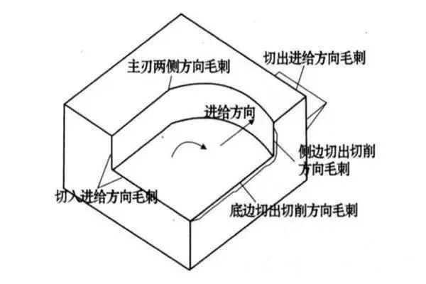
1. The main form of Burrs during end-end processing

According to the cutting movement – the cutting blade of the cutting blade remains classification system, the land produced during the final milling process mainly includes the wads on both sides of the main blade, the cutting direction of the cutting direction cutting on the side, cutting Direction of the cutting direction, and cutting and cutting in the bottom, there are five shapes of burrs (see Figure 1).

Figure 1 Burrs formed by milling processing

Generally speaking, the cutting direction of the cutting direction is the characteristics of large size and elimination of difficulties compared with other burrows. To this end, this paper uses the lower edge of the cutting direction of the cutting direction as the main research object to carry out research. According to the sizes and shapes of the cutting direction of the cutting direction according to the final mill, it can be divided into three types: Type I (larger size, elimination of difficulties, higher expenses), II Burrs (the size is compared to the size that the size is compared small, it cannot be removed or deleted) and the type III burr is negative negative (as shown in Figure 2).

WeChat Picture_20230428094258.jpg

Figure 2 Cut out the cutting direction of the cutting direction when the bottom of the grinding

Second, the main factor affecting the formation of terrifying

The Burrs formation is a very complicated material deformation process. The characteristics of workpiece materials, geometric shapes, surface treatment, tool geometry, tool cutting path, tool wear, cutting parameters and coolant all directly affect the formation of the Burrs. Figure 3 shows the final flash factors. Under the specific grinding conditions, the shape and size of the final milling wad depends on the comprehensive effect of various influencing factors, but different factors have different effects on the formation of terrifyings.

WeChat Picture_20230428094308.jpg

Figure 3 Mison the terrifying to form the cause and effect control chart

01. Swords enter/exit

Under normal circumstances, the burrows generated by the knife tips are larger than the burrows generated when the tool is rotated across the room.

02. Cutting the plane

The cutting angle of the plane has a great impact on the formation of the cutting direction of the cutting direction. The definition of plane cutting angle is when the cutting blade rotates the terminal surface of the workpiece, in the plane of a small axis of vertical cutters on the cutting blade, the cutting speed of this point (the direction of the knife speed and speed Vector synthesis of the feed speed) and the speed of the feed speed)) the angle between the end faces of the workpiece. The direction of the end surface of the workpiece is to point the knife point to the knife point. As shown in Figure 5, the 面 is cut from the plane and its range is 0°<ψ≤180°.

The test results show that the height of the burrs changes with the change in the depth of the cut, that is, the increase in the terrifyings of the depth of the cutting depth of the transition from burr II to type II. The minimum milling depth of the Burr II is generally referred to as the limiting cutting depth, which is represented by DCR. Figure 6 shows the impact of plane rake angle and cutting depth on Burr height when processing aluminum alloy.

WeChat Picture_20230428094314.jpg

Figure 6 Cut Corner and Cutting Depth of Burrows and Plane Shape

It can be seen from Figure 6: the larger the graphic angle, the larger the boundary cutting depth, when the plane cut angle is greater than 120°, the size of type I has larger size and the limit and the limit Cut the depth of the limit of the type II type. Consequently, the small plane cuts the angle of burr II.

It can be seen from Figure 5: The size and direction of the feed speed will have a certain impact on the size and direction of the synthesis speed V, which will then affect the plane corner and the terrifying. Therefore, the larger the speed of the feed rate and the output edge, the smaller the ψ ψ, the more terrifying the formation of the formation (as shown in Figure 7).

WeChat Picture_20230428094318.jpg

fig

03, the tip of the EOS knife tip

During the end milling process, the size of the terrifyings depends to a large extent on the order of the knife output. As shown in Figure 8: point A is the point on the side cutting blade, point C is the point on the main cutting blade, and point B is the tip of the knife. Assume that the tip of the knife is sharp, i.e. do not consider the tip radius of the knife tip. If the BC leaves the room first, then leaves the room to the AB side, the chip hinge is on the treatment surface. Cut the cutting direction of the cutting direction. If AB leaves the workpiece first, BC leaves the workpiece, the crumbs are cut on the transition surface, and the workpiece is cut to form a smaller bottom edge to cut the cutting direction of the cutting direction .

The test shows that: ① The tip of the knife tip that increases the size of Burrs is: ABC / BAC / ACB / BCA / CAB / CBA. ② The result of EOS is the same, but in the same order of output, plastic materials are larger than the terrifying ones produced by crispy materials.

The output order of the knife tip is not only related to the geometric shape of the tool, but also related to factors such as feed volume, milling depth, geometric size of the workpiece and cutting conditions. affect the formation of the Burrs.

WeChat Picture_20230428094323.jpg

Figure 8 Knife tip formation and burrow formation

04. The influence of other factors

① The formation of milling parameters, milling temperature and cutting environment will also have a certain impact on the formation of terrifyings. The exit of the knife tip from the knife tip is reflected.

② The better the material of the part is plastic, the more likely it is to form I Type I. During the processing process of the end of fragile materials, if the quantity of intake or plane is large, it will be conducive to the formation of type III (deficiency);

③ When the angle between the terminal surface of the workpiece and the processed plane is greater than the right angle, it can inhibit the formation of terrifyings due to the enhancement of the terminal facial branches;

④ The use of milling fluid is conducive to extending the tool life, reduces tool wear and lubrication and milling process, thereby reducing land size;

⑤ Knife wear has a great impact on burr formation. But the cutting direction of the tool will be generated.

⑥ Other factors, such as tool materials, have a certain impact on the formation of Burrs. Under the same cutting conditions, diamond knives are more conducive to removing terrifying formation than other tools.

3. The basic way to control the formation of milling noise

The formation of terrifying endings is affected by various factors. To reduce the final burr, it is necessary to control and reduce the production of terrifyings in many aspects.

01. Reasonable structural design

The formation of Burrs is largely affected by the structure of the workpiece, the structure of the workpiece is different, and the shape and size of the terrifyings on the edge of the edge after processing are also very different. If the material and surface treatment of the parts are placed in advance, the geometric shape and edge of the part are an important factor in determining the formation of terrifyings.

02. Proper processing order

The processing order also has a certain impact on the shape and size of the milling holes. The shape and size of terrifyings are different, and the workload and related costs of eliminating terrifyings are also different. Figure 10 is the production of large terrins using the appropriate processing order.

WeChat Picture_20230428094328.jpg

Figure 9 Select Sequential Processing Control Method

If you drilled the hole first and then molding, the hole is prone to cutting grinding burrs on the weekly circle; Similarly, in Fig.

03. Avoid the exit knife

Avoiding tool exit is an effective way to avoid drag formation, because tool exit is the main factor in the formation of brake formation in the steering. Under normal circumstances, the terrifyings generated by the strawberry room are larger, and the terrifyings generated when entering the room are smaller. Therefore, during the processing process, try to avoid spinning strawberries. As shown in Figure 4, the earths born in Figure 4b are lower than the earths produced in Figure 4A.

04. Select the appropriate walking route

From the previous analysis, it can be seen that when the plane cuts the angle less than a certain value, the size of the terrifyings is smaller. The cutting angle of the plane can be changed by changing the grinding width, feed speed (size and direction) and rotation speed (size and direction). Therefore, you can avoid the production of Type I Burrs by selecting the correct knife path (see Figure 11).

WeChat Picture_20230428094333.jpg

Figure 10 Control the knife route method

Figure 10a is a traditional font line. Figure 10b adopts an improved knife path, which can avoid the production of terrifyings. Although the walking route in Figure 11b is slightly longer than the walking route in Figure 10A, and the spending time is slightly much, because the terrifyings are not needed, and the use of Figure 10A requires a lot of damage time (although the shadow part of the figure 10A (although the shadow part of the figure 10A (although the shadow part of the figure, the shadow part of Figure 10a requires it, there are not many parts of the burr, but all the edges of the Burrs when The terrifyings are actually removed).

05. Select appropriate milling processing parameters

The end milling parameters (such as the quantity of each tooth, the width of the end milling, the depth of the end milling and the geometric angle of the tool) have a certain effect on the formation of burrs.

The formation of terrifying endings is affected by various factors. The final shape and size of the Burrs are the result of the comprehensive effect of various factors.

This article starts from the whole process of structure design, processing layout, processing processing, milling quantity and tool selection, analyzes the main influencing factors milling wads and offers to control the milling cutter control method, Select the appropriate processing order method and the improvement of the improvement of the structural design. shorten the production cycle in grinding processing.

Daguang focuses on providing solutions such as precision CNC machining services (3-axis, 4-axis, 5-axis machining), CNC milling, 3D printing and rapid prototyping services.

CNC Experts

Picture of JinShui Chen

JinShui Chen

Rapid Prototyping & Rapid Manufacturing Expert

Specialize in CNC machining, 3D printing, urethane casting, rapid tooling, injection molding, metal casting, sheet metal and extrusion

CNC Recent Posts

CNC News

Welcome to GreatLight Metal,Maximum Processing Size 4,000 mm

Precision Machining CNC Quote Online

Loading file

Upload Click here to upload or drag and drop your model to the canvas.

The model is too large and has been resized to fit in the printer's build tray. [Hide]

The model is too large to fit in the printer's build tray. [Hide]

The model is too large, a fitting printer is selected. [Hide]

The model is too small and has been upscaled. [Hide]

Warning: The selected printer can not print in full color [Hide]

Warning: obj models with multiple meshes are not yet supported [Hide]

Warning: Unsupported DXF entity  [Hide]

Warning: could not arrange models [Hide]

[Hide]


File Unit:      
Scale:
%
L × W × H:
X: × Y: × Z:  cm 
Rotation:
X: ° Y: °  
⚡ Instant Quote for Precision Manufacturing

Submit your design files (STEP/IGES/DWG) and receive a competitive quote within 1 hour, backed by ISO 9001-certified quality assurance.

📋 How It Works

  1. Upload & SpecifyShare your 3D model and select materials (Aluminum/Stainless Steel/Titanium/PEEK), tolerances (±0.002mm), and surface treatments.

  2. AI-Powered AnalysisOur system calculates optimal machining strategy and cost based on 10+ years of automotive/aerospace data.

  3. Review & ConfirmGet a detailed breakdown including:
    - Volume pricing tiers (1-10,000+ units)
    - Lead time (3-7 days standard)
    - DFM feedback for cost optimization

Unit Price: 

Loading price
5 Axis CNC Machining Equipment
4 Axis CNC Machining Equipment
3 Axis CNC Machining Equipment
CNC Milling & Turning Equipment
Prototype and Short-Run Injection Moldings Exact plastic material as final design
Volume Metal Die Casting Services - Precision Cast Parts
Bridge the Gap From Prototype to Production – Global delivery in 10 days or less
Custom high-precision sheet metal prototypes and parts, as fast as 5 days.
Custom Online 3D Printing Services
Design Best Processing Method According To 3D Drawings
Alloys Aluminum 6061, 6061-T6 Aluminum 2024 Aluminum 5052 Aluminum 5083 Aluminum 6063 Aluminum 6082 Aluminum 7075, 7075-T6 Aluminum ADC12 (A380)
Alloys Brass C27400 Brass C28000 Brass C36000
Alloys Stainless Steel SUS201 Stainless Steel SUS303 Stainless Steel SUS 304 Stainless Steel SUS316 Stainless Steel SUS316L Stainless Steel SUS420 Stainless Steel SUS430 Stainless Steel SUS431 Stainless Steel SUS440C Stainless Steel SUS630/17-4PH Stainless Steel AISI 304
Inconel718
Carbon Fiber
Tool Steel
Mold Steel
Alloys Titanium Alloy TA1 Titanium Alloy TA2 Titanium Alloy TC4/Ti-6Al 4V
Alloys Steel 1018, 1020, 1025, 1045, 1215, 4130, 4140, 4340, 5140, A36 Die steel Alloy steel Chisel tool steel Spring steel High speed steel Cold rolled steel Bearing steel SPCC
Alloys Copper C101(T2) Copper C103(T1) Copper C103(TU2) Copper C110(TU0) Beryllium Copper
Alloys Magnesium Alloy AZ31B Magnesium Alloy AZ91D
Low Carbon Steel
Alloys Magnesium Alloy AZ31B Magnesium Alloy AZ91D
ABS Beige(Natural) ABS Black ABS Black Antistatic ABS Milky White ABS+PC Black ABS+PC White
PC Black PC Transparent PC White PC Yellowish White PC+GF30 Black
PMMA Black PMMA Transparent PMMA White
PA(Nylon) Blue PA6 (Nylon)+GF15 Black PA6 (Nylon)+GF30 Black PA66 (Nylon) Beige(Natural) PA66 (Nylon) Black
PE Black PE White
PEEK Beige(Natural) PEEK Black
PP Black PP White PP+GF30 Black
HDPE Black HDPE White
HIPS Board White
LDPE White
This is a finish of applying powdered paint to the components and then baking it in an oven, which results in a stronger, more wear- and corrosion-resistant layer that is more durable than traditional painting methods.
No coating required, product’s natural color!
This is a finish of applying powdered paint to the components and then baking it in an oven, which results in a stronger, more wear- and corrosion-resistant layer that is more durable than traditional painting methods.
This finishing option with the shortest turnaround time. Parts have visible tool marks and potentially sharp edges and burrs, which can be removed upon request.
Sand blasting uses pressurized sand or other media to clean and texture the surface, creating a uniform, matte finish.
Polishing is the process of creating a smooth and shiny surface by rubbing it or by applying a chemical treatmen
A brushed finish creates a unidirectional satin texture, reducing the visibility of marks and scratches on the surface.
Anodizing increases corrosion resistance and wear properties, while allowing for color dyeing, ideal for aluminum parts.
Black oxide is a conversion coating that is used on steels to improve corrosion resistance and minimize light reflection.
Electroplating bonds a thin metal layer onto parts, improving wear resistance, corrosion resistance, and surface conductivity.
This is a finish of applying powdered paint to the components and then baking it in an oven, which results in a stronger, more wear- and corrosion-resistant layer that is more durable than traditional painting methods.
Please provide additional text description for other surface treatment requirements!
Material
Material
  • CNC Metals
    • Aluminum
    • Brass
    • Stainless steel
    • Inconel718
    • Carbon Fiber
    • Tool Steel
    • Mold Steel
    • Titanium
    • Alloy Steel
    • Copper
    • Bronze
    • Low Carbon Steel
    • Magnesium
  • CNC Plastics
    • ABS
    • PC
    • PMMA (Acrylic)
    • PA (Nylon)
    • PE
    • PEEK
    • PP
    • HDPE
    • HIPS
    • LDPE
Printer
Printer
  • CNC Metals
    • 5 Axis CNC Machining
    • 4 Axis CNC Machining
    • 3 Axis CNC Machining
    • CNC Milling & Turning
    • Rapid Tooling
    • Metal Die Casting
    • Vacuum Casting
    • Sheet Metal Fabrication
    • SLA 3D Printing
    • SLS 3D Printing
    • SLM 3D Printing
  • Rapid Prototyping
    • Design Best Processing Method According To 3D Drawings
Post-processing
Post-processing
  • As Machined(Product’s natural color)
  • Sand Blasting
  • Polishing
  • Brushed Finish
  • Anodizing
  • Black Oxide
  • Electroplating
  • Paint Coating
  • Powder Coating
  • Other surface treatment requirements
Finalize
The world's first CNC machining center that dares to provide free samples!

Free for first product valued at less than $200. (Background check required)

precision machining cnc quote online

15 Years CNC Machining Services

When you’re ready to start your next project, simply upload your 3D CAD design files, and our engineers will get back to you with a quote as soon as possible.
Scroll to Top

ISO 9001 Certificate

ISO 9001 is defined as the internationally recognized standard for Quality Management Systems (QMS). It is by far the most mature quality framework in the world. More than 1 million certificates were issued to organizations in 178 countries. ISO 9001 sets standards not only for the quality management system, but also for the overall management system. It helps organizations achieve success by improving customer satisfaction, employee motivation, and continuous improvement. * The ISO certificate is issued in the name of FS.com LIMITED and applied to all the products sold on FS website.

greatlight metal iso 9001 certification successfully renewed
GB T 19001-2016 IS09001-2015
✅ iso 9001:2015
greatlight metal iso 9001 certification successfully renewed zh

IATF 16949 certificate

IATF 16949 is an internationally recognized Quality Management System (QMS) standard specifically for the automotive industry and engine hardware parts production quality management system certification. It is based on ISO 9001 and adds specific requirements related to the production and service of automotive and engine hardware parts. Its goal is to improve quality, streamline processes, and reduce variation and waste in the automotive and engine hardware parts supply chain.

automotive industry quality management system certification 01
Certification of Production Quality Management System for Engine Hardware Parts Engine Hardware Associated Parts
automotive industry quality management system certification 00
发动机五金零配件的生产质量管理体系认证

ISO 27001 certificate

ISO/IEC 27001 is an international standard for managing and processing information security. This standard is jointly developed by the International Organization for Standardization (ISO) and the International Electrotechnical Commission (IEC). It sets out requirements for establishing, implementing, maintaining, and continually improving an information security management system (ISMS). Ensuring the confidentiality, integrity, and availability of organizational information assets, obtaining an ISO 27001 certificate means that the enterprise has passed the audit conducted by a certification body, proving that its information security management system has met the requirements of the international standard.

greatlight metal technology co., ltd has obtained multiple certifications (1)
greatlight metal technology co., ltd has obtained multiple certifications (2)

ISO 13485 certificate

ISO 13485 is an internationally recognized standard for Quality Management Systems (QMS) specifically tailored for the medical device industry. It outlines the requirements for organizations involved in the design, development, production, installation, and servicing of medical devices, ensuring they consistently meet regulatory requirements and customer needs. Essentially, it's a framework for medical device companies to build and maintain robust QMS processes, ultimately enhancing patient safety and device quality.

greatlight metal technology co., ltd has obtained multiple certifications (3)
greatlight metal technology co., ltd has obtained multiple certifications (4)

Get The Best Price

Send drawings and detailed requirements via Email:[email protected]
Or Fill Out The Contact Form Below:

All uploads are secure and confidential.