
Bulk Rapid Tooling Fabrication Process
This guide walks through the bulk rapid tooling fabrication process used to build a family of matched molds, dies or fixtures in one compressed cycle. It is written for tooling engineers and sourcing managers who need to plan machine time, hold cavity-to-cavity tolerance, and decide when bulk tooling makes sense over single-tool or bridge tooling.
In this article
- 1
- 2
- 3
- 4
- 5
- 6
- 7
- 8
- 9
Key takeaways
What the bulk rapid tooling fabrication process actually covers
The bulk rapid tooling fabrication process is the planned, concurrent production of several functional tools, usually injection molds, die casting dies or stamping dies, inside one compressed schedule. A single rapid tool proves a design. A bulk run delivers a matched set, so two to six presses or cells can run the same part at the same time.
That word bulk changes the engineering problem. On one mold you can hand-fit a slide or shim a core. On twelve molds you cannot, because every manual adjustment adds variance you cannot track later. Tooling families live or die on replication: the same electrode, the same tool path template, the same fixture datum, repeated without operator judgment.
Tooling classes stay useful as a rough map. Prototype tooling serves a few hundred shots. Bridge tooling serves 10,000 to 100,000 parts. Production tooling runs into the millions. Bulk rapid tooling sits between bridge and production: hardened or pre-hardened steel, real cooling circuits, and a finish that holds up across the whole family, delivered fast enough to matter.
Where it fits best is a program that needs multiple identical tools quickly, often for parallel molding sites or for several product variants sharing a base. Where it fits badly is a design still in flux. Lock a family of molds around a geometry that will move in three weeks and you have bought twelve problems.
- 1Typical family size4 to 40 tools per program, built in one batch.
- 2Best-fit partsMolds, die casting dies, stamping dies, holding fixtures.
- 3Steel you will seeP20, H13, 420 stainless, 17-4PH, tool steel grades.
- 4When to stopDesign frozen, volume confirmed, press list confirmed.
Design for tooling multiplicity before any metal is cut
Multiplicity planning starts in CAD, not on the shop floor. Cooling lines should follow a mirrored layout so the same drilling program works on every plate. Ejector pin positions get grid-based coordinates instead of hand-placed points. Alignment uses dowels and taper locks, never a machined boss that only one operator can fit by feel.
Tolerances need a family budget, not a part budget. If cavity A sits at plus 0.02 mm and cavity B at minus 0.02 mm, the parts still assemble, but scrap rates double. Split the tolerance across the cavity, the core, the shut-off and the plate stack so each feature owns a share you can measure and sign off.
Gate and runner design deserves the same treatment. A hot runner with identical drops keeps fill balance predictable across tools. Cold runners work too, but each tool then needs its own fill study, which slows the batch and adds cost per tool. Choose the option that matches your volume and your press list.
Draft and corner radii are the quiet killers. Add 1° to 4° of draft on walls over 50 mm tall, and avoid sharp internal corners on tool steel where stress cracking starts. A radius that looks fine on a rendering costs one EDM electrode per tool, multiplied by the family size.
- 1Mirror the cooling layoutSame circuit on every plate of the family.
- 2Standardize datumsOne zero point for CAD, CAM, CMM and benchwork.
- 3Budget tolerance per featureCavity, core, shut-off and plate stack each own a share.
- 4Check draft early1° to 4° on tall walls prevents drag marks.
Digital twin simulation and process planning
CAM simulation verifies every tool path before a spindle turns. For a tooling family the goal is different from a one-off: you are testing whether one master program can be parameterized across all cavities. Program the first cavity in full, prove it, then drive the rest from a coordinate table and a stock model.
Run collision checks on the longest tools in the batch. Deep ribs and narrow slots force small-diameter cutters with long gauge lengths, and those are where crashes happen. A 5-axis simulation that includes the holder, the fixture and the rotary table catches interference that a 3-axis check will miss.
Mold flow analysis answers a different question. Fill balance, weld line position and cooling time should match across cavities. If one cavity runs 8 s slower to eject, the whole family inherits that bottleneck. Fix the cooling layout in simulation, where changes cost nothing.
Aim for a repeatable process window rather than one perfect result. You want a range of injection pressures, hold times and cooling durations where every cavity in the family produces an acceptable part. Record that window and hand it to the tryout team as a target, not a guess.
- 1Master program firstProve one cavity, then parameterize the rest.
- 2Simulate the long toolsCheck holder and fixture clearance in 5-axis.
- 3Balance cooling timeKeep cavity-to-cavity cycle spread under 1 s.
Material pre-conditioning and parallel machining
Pre-hardened and hardened blocks arrive with internal stress. Cut the cavity first and the steel moves, then the shut-off no longer seals. Rough out 3 to 5 mm of stock, stress relieve where the grade allows, and finish after the material has settled. H13 and 420 stainless especially repay this step.
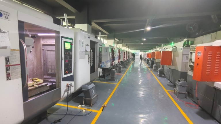
Order pre-cut blocks to fit the work envelope of the machines you intend to run in parallel. With 127 CNC machines on the floor and 16 simultaneous 5-axis centers, we can spread a family across several spindles at once. Long travel machines handle up to 4,000 mm, while the 750 × 1,150 × 550 mm and 600 × 600 × 600 mm envelopes cover most mold plates.
Parallel machining only works with a shared setup. Fixture plates get the same pin positions on every machine. Tool offsets and probing routines are loaded from one file. If two operators set up the same operation in two different ways, you have built two different tools, not a matched pair.
Track every plate through a traveler with operation numbers, machine ID and probe results. When plate 7 measures 0.01 mm off, the traveler tells you whether the cause is the setup, the tool wear or the stock. Without it you are guessing across 40 plates.
- 1Rough, relieve, finishLeave 3 to 5 mm stock before stress relief.
- 2Pre-cut to envelopeMatch block size to spindle travel before purchase.
- 3One setup fileShared offsets and probe cycles across machines.
- 4Traveler per plateOperation, machine ID and probe data on one sheet.
High-speed CNC machining and EDM integration
High-speed milling removes most of the cavity volume, then EDM finishes the corners, ribs and shut-offs that a cutter cannot reach. The handoff point matters. Leave 0.2 to 0.5 mm of EDM stock on surfaces the electrode will burn, and machine everything else to size so the burn time stays short.
5-axis machining with a Ø400 mm rotary table lets you cut deep cavities, angled gates and conformal cooling channels in fewer setups. Each setup you remove is one less chance to lose the datum. On a family of tools, that saving multiplies by the number of plates.
Electrode management is the hidden schedule risk. A ribbed cavity can need 15 to 30 electrodes, and roughing and finishing electrodes must be tracked separately. Number them, log wear, and burn in a fixed order so electrode 12 on tool 1 and electrode 12 on tool 8 do the same job.
Watch heat. Thin ribs and long electrodes distort when copper or graphite gets too hot, and the burn gap closes. Use peck cycles, flush the gap properly and check the first cavity before committing the rest of the batch.
- 1Milling leaves EDM stock0.2 to 0.5 mm on burned surfaces only.
- 2Rotary table saves setupsØ400 mm table handles most angled features.
- 3Number every electrode15 to 30 per ribbed cavity is normal.
- 4Check cavity oneVerify burn gap before running the batch.
Metrology and in-process verification
Measure after roughing, not only at the end. A CMM check on the first cavity confirms the program, the fixture and the thermal state of the machine. If the cavity is drifting, you catch it while there is still stock to remove, not after the shut-off is finished.
The tolerance target for tooling work is ±0.005 mm on critical fits, with surface finish held to Ra 0.8–1.6 μm on sealing and sliding surfaces. Fine finishes down to Ra 0.2–0.8 μm are available where a polished cavity or a sliding core needs it. Not every surface needs that. Spending it everywhere slows the batch for no gain.
Run the same measurement routine on every plate. Same probe, same alignment, same temperature. A shop that measures cavity 1 at 20 °C and cavity 9 at 26 °C will report differences that are thermal, not dimensional, and chase problems that do not exist.
Reports go to the customer on request. Raw material certificates, in-process probe logs and final CMM data should travel with the tooling. When the molds reach a different plant, that paperwork is the only record of what nominal actually meant.
- 1Probe after roughingCatch drift while stock remains.
- 2Critical fits at ±0.005 mmSealing and sliding surfaces at Ra 0.8–1.6 μm.
- 3Same routine, same tempMeasure every plate the same way.
- 4Ship the dataCertificates and CMM reports with the tooling.
Step by step through a bulk tooling build
Seven stages, from frozen design to signed-off tooling family.
- 11. Freeze the design and the family sizeConfirm part geometry, annual volume, press list and number of tools. Do not start cutting until the part drawing is locked. Changing a wall thickness after cavity one is burned costs an electrode set per tool.
- 22. Run DFTM and split the tolerance budgetMirror cooling, standardize ejector grids, define one datum. Assign tolerance shares across cavity, core, shut-off and plate stack so each feature can be measured. Expect 1° to 4° of draft on walls over 50 mm.
- 33. Simulate and templatize the CAMProve the master program on cavity one, then parameterize. Run 5-axis collision checks with holder and fixture models. Run mold flow to balance fill and keep cavity cycle spread under 1 s.
- 44. Pre-condition and rough in parallelOrder pre-cut blocks to machine envelope. Rough leaving 3 to 5 mm, stress relieve, then finish. Spread plates across multiple spindles using shared fixture pin positions and one offset file.
- 55. Machine high-speed, then burn with EDMLeave 0.2 to 0.5 mm EDM stock on burn surfaces only. Use the Ø400 mm rotary table to cut angled features in fewer setups. Number every electrode and burn in a fixed sequence across the family.
- 66. Verify after roughing and after finishingCMM the first cavity early. Hold ±0.005 mm on critical fits and Ra 0.8–1.6 μm on sealing surfaces. Measure every plate with the same routine at the same temperature. Log results on the traveler.
- 77. Benchwork, assembly and tryoutFit slides and lifters by hand where needed, then assemble and check shut-off with blueing. Run tryout shots, record the process window, and adjust cooling or gate trim only if a cavity falls outside it. Sign off dimensional and cosmetic criteria together.
Traditional tooling vs. rapid tooling vs. bulk rapid tooling
Use this to pick the class before you commit steel.
| Factor | Traditional tooling | Rapid tooling | Bulk rapid tooling |
|---|---|---|---|
| Number of tools | One at a time | One tool | 4 to 40 in one batch |
| Typical lead time | Weeks to months per tool | Days to a few weeks | Days for the whole family |
| Steel | Hardened production grades | Aluminum or soft steel | P20, H13, 420, 17-4PH |
| Part volume fit | Millions of shots | Hundreds to low thousands | 10,000 to 100,000+ parts |
| Tool life | Longest | Shortest | Medium to long |
| Cost per tool | Highest | Lowest | Lower than traditional |
| Replication risk | Low, one tool | Not applicable | High, needs process control |
| Best use case | Single high-volume product | Design validation | Parallel molding or press sites |
When bulk tooling is the right call
If the design is frozen, the volume is confirmed and you need several identical tools running at once, bulk rapid tooling pays for itself. If any of those three is still moving, build one bridge tool first and revisit the family later.
Common questions about bulk rapid tooling
How many tools count as a bulk run?
In practice, a family starts around 4 tools and runs to about 40 in one batch. Below four, the setup and programming overhead per tool rarely justifies the coordination work, and a single rapid tool or two bridge tools usually get you to production faster.
Above 40, the schedule risk shifts to electrode supply and CMM queue time rather than machining capacity, so the batch is often split into two waves.
What tolerance can you hold across a family of molds?
Critical fits are held to ±0.005 mm (±0.0002 in), with sealing and sliding surfaces finished to Ra 0.8–1.6 μm. Finer finishes down to Ra 0.2–0.8 μm are available where a polished cavity or sliding core needs it.
Cavity-to-cavity consistency matters more than the absolute number. Every plate is measured with the same routine at the same temperature so differences you see are dimensional, not thermal.
Which materials are used for bulk rapid tooling?
Common choices are P20 for medium-volume molds, H13 for die casting dies, 420 and 17-4PH stainless for corrosive resins or medical work, and 4130 or 4140 for stamping and fixtures. Aluminum grades like 7075 suit bridge tooling where cycle count is low.
Material selection follows the resin, the cycle count and the cooling requirement, not the other way around.
How is dimensional data verified and reported?
Every plate gets raw material checks, in-process probing after roughing and final CMM inspection before shipment. Inspection is 100% before the tooling leaves the shop.
Reports are available on request and travel with the tooling, which matters when the molds are installed at a different plant from where they were built.
What is the most common failure in a bulk tooling project?
Starting before the design is frozen. A geometry change after cavity one is burned forces a new electrode set for every tool in the family, and the schedule slips by the number of tools, not by one.
The second most common failure is inconsistent setup. Two operators setting up the same operation differently produce two different tools, which shows up later as unbalanced fill.
Can a bulk tooling family be split across sites?
Yes, and that is often the point. Shared datums, numbered electrodes and one measurement routine make it possible for tools built in the same batch to run in different plants and produce matching parts.
The paperwork has to travel with the steel. Certificates, probe logs and CMM reports are what let a second site confirm it received nominal tooling.
How does confidentiality work on tooling projects?
Uploads are secure and confidential, and an NDA is available on request before drawings are shared. ISO 27001:2022 certification covers information security management at the company level.
If your program requires restricted data handling, say so at the quote stage so the project is set up correctly from the start.
Plan your tooling family with the numbers in hand
Send the part drawing, the target volume and the number of tools you need. You get a quotation and a free DFM analysis within 12 hours, and we will tell you if a single bridge tool is the better first move.
12-hour quote100% inspectionNDA on requestNo minimum order quantity
More from the shop floor
We publish setup notes, tooling trials and inspection data from the factory floor.











