The design of tool lighting is generally carried out after the formulation of the mechanical processing process of parts as a function of the specific requirements of a certain process. During the formulation of the process, the possibility of implementing the luminaire must be fully taken into account. The quality of design of the tooling light must be measured by the question of whether it can stable the quality of treatment of the part, high production efficiency, low cost, practical elimination of fleas, operation Sure, an economy of labor and easy manufacturing and maintenance.
The quality of design of the tooling light must be measured by the question of whether it can stable the quality of treatment of the part, high production efficiency, low cost, practical elimination of fleas, operation Sure, an economy of labor and easy manufacturing and maintenance.
1. Basic principles of the design of the luminaire
1. Satisfy the stability and reliability of the positioning of the part during use;
2. Have enough loading or tightening force to ensure the process of processing the part on the tool lighting;
3. Cleans up the simple and easy operation during tightening;
4. Vulnerable parts should be quickly replaced.
5. Respond to the reliability of the repeated positioning of the luminaire during adjustment or replacement;
6. Avoid complex structure and costly cost as much as possible;
7. Choose standard parts as components as possible;
8. Form the systemization and normalization of internal products of the company.
2. Basic knowledge of the tools and the design of lighting
An excellent machine-tool luminaire must meet the following basic requirements:
1. Ensure the machining accuracy of the part. The key to ensuring the precision of the machining is to correctly select the positioning reference, the positioning method and the positioning components. The luminaire can meet the rooms for machining the room.
2. Improve production efficiency. The complexity of special lights must be consistent with the production capacity situation, and various fast and effective tightening mechanisms must be used as much as possible to ensure easy operation, shorten the auxiliary time and improve production efficiency.
3. Good process performance. The structure of special lights must be simple and reasonable, and be practical for manufacturing, assembly, adjustment, inspection, maintenance, etc.
4. Good performance. Tool lights must have sufficient resistance and rigidity, and must be easy to use, save work, safe and reliable. Under the premise that the objective conditions allow and economical and applicable, mechanized tightening devices such as pneumatic and hydraulic should be used as much as possible to reduce the intensity of the operator’s work. Working devices must also be practical for eliminating fleas. If necessary, the elimination structures of fleas can be configured to prevent fleas from destroying the positioning of the room and damaging the tool, and preventing the accumulation of shavings from causing a large amount of heat to cause the deformation of the process system.
5. Good economy. Special lights should use standard components and standard structures as much as possible, and endeavor to be simple in structure and easy to make to reduce the manufacturing cost of lighting. Consequently, during the design, the necessary technical and economic analysis of the luminaire plan must be carried out according to the control and the production capacity to improve the economic advantages of the lighting in production.
3. Presentation of the standardized design of tool lights
1. Basic methods and tool design stages
Original information to prepare the design of the tool lighting before design include the following content:
(1) Design notice, finished part drawing, blank drawing and process route and other technical information, understand the technical requirements for processing each process, positioning and tightening plan, content of the previous process, the situation of The ignition, the machine tools used in the treatment, tools, inspection and measurement tools, treatment allocation and use of the cut, etc.;
(2) Understand the production batch and the demand for lighting;
(3) Understand the main technical parameters, performance, specifications, the accuracy of the machine machine used and the connection dimensions of the structure of the lighting room, etc.;
(4) Inventory of standard lighting materials.
2. Problems in the design of tool lighting
The design of the luminaire has generally a single structure, which gives people the feeling that the structure is not very complicated. Unnecessary problems will inevitably occur:
(1) The white room margin to be treated. This makes the size empty too large and interferes. Therefore, you need to prepare an empty drawing before design. Leave enough space.
(2) The softness of withdrawal of the chips from the luminaire. During the design, due to the limited treatment space of the tooltip, the light is often designed with a relatively compact space. A bad flow of chip liquid, which will be given in the future. Therefore, the problems that arise during the processing process should be taken into account at the start of real practice.
(3) The overall opening of the luminaire. The ignorance of the opening makes it difficult for operators to install cards, long-lasting and a high intensity of labor, and a design taboo.
(4) Basic theoretical principles of the design of the luminaire. Each set of lights must undergo countless tightening and relaxation actions, it can therefore meet the requirements of the user at the beginning, but the addition should have its precision retention, so do not design something that is contrary to Principles. Even if you may have the chance to do it now, there will be no long -term sustainability. Good design must be tempered by time.
(5) Replacement of the positioning element. The positioning elements are seriously worn, therefore a quick and practical replacement must be taken into account. It is best not to design in larger parts.
The accumulation of experience in the design of the luminaire is very important.
The current tools are mainly divided into features types: ① Tightening mold; Tools; ⑦ Polishing polishing;
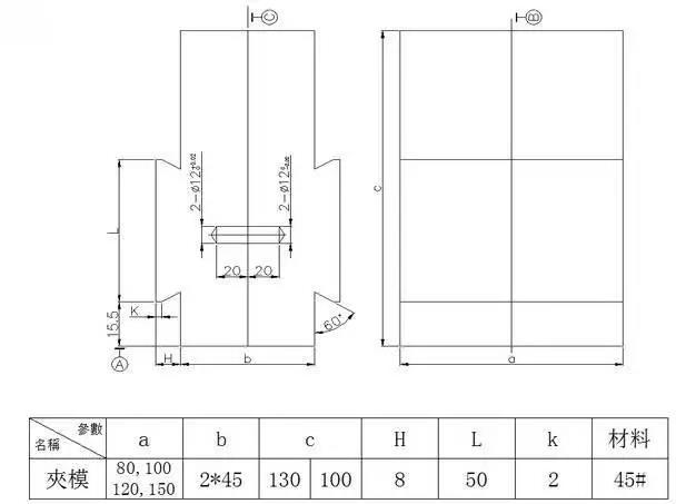
1. Clip mold
Definition: Tools for positioning and tightening using the appearance of the product.
Design points:
1. This type of tightening mold is mainly used on visors, and its length can be intercepted if necessary;
2. Other auxiliary positioning devices can be designed on the clamping mold, and the clamping mold is generally connected by welding;
3. The image above is a simplified image, and the size of the structure of the mold cavity is determined by the specific situation;
4. Attach the positioning pin of the diameter 12 to the appropriate position on the mobile sector and slide the positioning holes with the corresponding positioning mold to adjust the positioning pin;
5. When designing the assembly cavity, it must be shifted and widened by 0.1 mm as a function of the appearance surface of the virgin pattern without narrowing.
2. Drilling and milling part
Design points:
1. If necessary, some auxiliary positioning devices can be designed on the fixing nucleus and its fixing plate;
2. The image above is a structural diagram, and the real situation requires a corresponding design based on the structure of the product;
3. The cylinder depends on the size of the product and the constraint during treatment, and SDA50X50 is commonly used.

3. CNC, Chuck instrument, a CNC mandrel, inner beam chuck

Design points:
1. The dimensions not marked in the above figure are determined by the inner size structure of the real product;
2. The outer circle in contact with the positioning of the inner hole of the product must be left with a margin of 0.5 mm on one side during production, and finally install it on the CNC machine to obtain the size to prevent the deformation and eccentricity caused by the caliber process;
3. It is recommended to use spring steel for the assembly part, and the shooting shooting part is 45 #;
4. The M20 wire of the shooting part is a common thread, and the wire can be adjusted according to the real conditions.
Interior chuck of the instrument

Design points:
1. The above figure is a reference diagram, and the size and structure of the assembly are determined as a function of the appearance dimension structure of the real product;
2. Use 45 # for the material and the processing of extinction.
Exterior chuck of the instrument

Design points:
1. The image above is a reference diagram, and the actual size depends on the size structure of the inner hole of the product;
2. The external circle in contact with the positioning of the inner hole of the product must be left with a margin of 0.5 mm on one side during the production, and finally install it on the tower of the instrument to refine it to prevent deformation and eccentricity caused by the caliber process;
3. Use 45 # for material and caliber.
4. Gas testing equipment

Design points:
1. The image above is a reference image for the gas test tool. be detected to be filled with gas to confirm its sealing properties;
2. The size of the cylinder can be adjusted according to the actual size of the product, and it is also necessary to determine whether the cylinder race can respect the convenience of the picking and the implementation of the product;
3. The sealing surface in contact with the product is generally made of ULI glue, NBR rubber ring and other materials with good compression. product surface.
4. The product positioning direction must be taken into account when designing to prevent gas leak inside the product’s cavity from causing poor verification.
5. Punching Piece

Design points:
The image above shows the common structure of the punching tools. The lower plate acts as practical for fixing on the trousseau of the punch machine; and picked up safely and placed; The assembly position and the size of the above parts can be designed depending on the real product situation.
6. Welding equipment
The welding tool mainly corrects the positions of each component in the welding assembly, controls the relative size of each component in the welding assembly, and its structure is mainly a positioning block, which must be designed as a function of the actual structure of the product. It should be noted that the sealing space should not be created between the products when placed on welding tools, in order to avoid excessive pressure space pressure during the welding of welding Allow the size of the parts after welding.
7.


8. Assembly work
The assembly tool is mainly used in the component assembly process that helps positioning. The design idea is to collect easily and place the product as a function of the assembly structure, and the appearance surface of the product cannot be damaged during assembly and cover with cotton fabric during the use to protect the product. When you choose materials, try to use non -metallic materials such as white glue.
9. Pad printing, laser lettering work clothes

Design points:
Design the tool positioning structure as a function of the real product engraving requirements. the product.
Daguang focuses on providing solutions such as precision CNC machining services (3-axis, 4-axis, 5-axis machining), CNC milling, 3D printing and rapid prototyping services.


