1. Types and types of welded joints
During welding, due to the different thicknesses, structures and usage conditions of the weld, the joint type and groove shape are also different. Types of weld joints include: butt joints, T-shaped joints, corner joints and lap joints, etc.
(1) Butt joint
A joint where the surfaces of two parts form an angle greater than or equal to 135° and less than or equal to 180° is called a butt joint. This is the most commonly used type of joint among various welding structures.
The thickness of the steel plate is less than 6mm. Except for important structures, there is generally no groove.
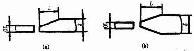
When the thickness difference (δ-δ1) between two steel sheets of different thicknesses butted together does not exceed the requirements of Table 1-2, the basic shape and size of the weld groove should be selected according to size data for the thickest sheet. ; otherwise, the thickness of the weld groove should be selected according to the size data of the thickest plate. Single-sided or double-sided thinning is carried out as shown in Figure 1-8, the thinning length L ≥ 3 (δ-δ1 ; ).
(a) Single-sided thinning (b) Double-sided thinning
Table 1-2
Thinner plate thickness δ1 | ≤2~5 | >5~9 | >9~12 | >12 |
Allowable thickness difference (δ-δ1) | 1 | 2 | 3 | 4 |
(2) Corner joint
A joint where the angle between the end faces of two weldments is greater than 30° and less than 135° is called a corner joint, see Figure 1-9. This type of joint does not resist stress very well and is often used in unimportant structures.

(a) I-shaped groove (b) V-shaped groove on one side with rounded edge
Figure 1-9 Corner joint
(3) T-shaped joint
A joint in which the end surface of one part forms a right angle or approximately a right angle to the surface of another part is called a T-shaped joint, see Figure 1-10.

Figure 1-10 T-shaped joint
(4) Lap joints
A joint formed by the partial overlap of two parts is called a lap joint, see Figure 1-11.

(a) I-shaped groove (b) plug welding in a round hole (c) fillet welding in a long hole
Figure 1-11 Lap joint
According to their structural form and strength requirements, lap joints are divided into three forms: without groove, plug welding in round hole and fillet welding in long hole, see Figure 1-11.
I-shaped lap joints are generally used for steel sheets with a thickness of less than 12mm. The overlapping part is ≥ 2 (δ1 + δ2) and are welded on both sides. This type of joint is used in unimportant structures.
When the overlap area is large, different sizes and numbers of plug welds in round holes or fillet welds in long holes can be used depending on the plate thickness and strength requirements.
2. Basic shapes and dimensions of weld grooves
(1) Beveled shape
According to the shape of the groove, the groove is divided into I shape (without groove), V shape, Y shape, double Y shape, U shape, double U shape, single sided V shape, Single-sided double Y, J shape, etc. A wedge shape.
V-shaped and Y-shaped grooves are easy to process and weld (no need to flip the weld), but they are subject to angular deformation after welding.
The double Y-shaped groove is developed on the basis of the V-shaped groove. When the thickness of the weld increases, the double Y-shaped groove is used instead of the V-shaped groove. the same thickness, the amount of metal in the weld can be reduced by about 1/2, and the welding can be reduced. carried out symmetrically and the residual deformation after welding is low. The disadvantage is that during the welding process, the solder must be turned over and welded inside the cylindrical solder, which worsens the working conditions.
The amount of filler metal of a U-shaped groove is much smaller than that of a V-shaped groove under the same weld thickness, but the processing of this type of groove is more complicated.
(2) Geometric dimensions of the groove
(1) Groove surface The groove surface on the parts to be welded is called the groove surface.
(2) Groove surface angle and groove angle. The angle between the end surface of the groove to be processed and the groove surface is called the groove surface angle. The angle between the two groove surfaces is called the groove angle. 12.
(3) Root space The space reserved between the roots of the joint before welding is called root space, see Figure 1-12. Its function is to ensure root penetration when welding from below. Root space is also called assembly space.
(4) Blunt edge When the weldment is grooved, the part of the straight edge of the end face along the root of the weldment joint groove is called the blunt edge, see Figure 1-12. The purpose of the blunt edge is to prevent the roots from burning.
(5) Root radius The fillet radius at the bottom of the J-shaped and U-shaped grooves is called the root radius (see Figure 1-12). Its function is to increase the space at the root of the groove so that the root can be welded all the way through.

Figure 1-12 Geometric dimensions of the groove
3. Types of welding stations
According to the provisions of GB/T3375-94 “Welding Terminology”, the welding position, that is, the spatial position of the weld joint during welding, can be expressed by the inclination angle of the weld and the angle of the weld. There are flat welding, vertical welding, horizontal welding and overhead welding stations.
The weld tilt angle is the angle between the weld axis and the horizontal plane, see Figure 1-13.

Figure 1-13 Weld tilt angle
The weld angle is the angle between the weld centerline (the line connecting the center of the weld root and the cover layer) and the Y axis of the horizontal reference plane, see Figure 1-14 .

Figure 1-14 Weld corner
(1) Flat welding position: The welding position with a weld tilt angle of 0° and a weld rotation angle of 90° is shown in Figure 1-15(a).

(a) Flat welding (b) Horizontal welding (c) Vertical welding (d) Overhead welding (e) Flat angle welding (f) Overhead angle welding
Figure 1-15 Different welding positions
(2) Horizontal welding position: the tilt angle of the weld is 0°, 180°; the welding bead rotation angle is 0°, butt position 180°, see Figure 1-15 (b).
(3) Vertical welding position: The welding position with welding tilt angle of 90° (vertical upward) and 270° (vertical downward) is shown in Figure 1-15 (c).
(4) Height welding position: the inclination angle of the butt weld is 0°, 180°. The welding position with a rotation angle of 270° is shown in Figure 1-15(d).
Additionally, two other welding positions are specified for fillet welding stations.
(5) Flat fillet welding position: the angle of the fillet weld is 0°, 180°; the angle of fillet welding is 45°, 135°, see Figure 1-15 (e).
(6) Elevation angle welding position: tilt angle 0°, 180°; angle welding position of 225°, 315°, see Figure 1-15(f).
Welding carried out in flat welding position, horizontal welding position, vertical welding position and overhead welding position are called flat welding, horizontal welding, vertical welding and overhead welding respectively. Welding T-shaped, cross-shaped and angle joints in flat welding position is called boat welding. Horizontally fixed pipe welding commonly used in engineering is called all-position welding because there are overhead welding, vertical welding and flat welding in 360° pipe welding. Welding carried out when the joint of the weldment is placed in an inclined position (except for flat, horizontal, vertical and overhead welding positions) is called tilt welding.
4. Shape, shape and size of the weld bead
(1) Shape of weld bead
Welds can be divided into the following forms according to different classification methods:
(1) According to the provisions of GB/T 3375-94, according to the shape of the welding joint, it is divided into five types: butt weld, fillet weld, plug weld, groove weld and fillet weld. end:
1) Butt weld: a weld between the groove surface of a weldment or between the groove surface of one part and the surface of another part,
2) Fillet weld: welding along the line of intersection of two orthogonal or nearly orthogonal parts.
3) End connection weld: The weld formed by the end connection joint.
4) Plug weld: Two pieces overlap, one of which has a round hole, and the weld formed by welding the two plates in the round hole. If only the fillet weld is welded in the hole, we don’t talk plug solder.
5) Slot welding: Two overlapping plates, one of which has a long hole, and the solder of the two plates is welded in the long hole. If only the fillet weld is welded, it is not called slot welding.
(2) According to the position of the weld in space during welding, it is divided into four forms: flat weld, vertical weld, horizontal weld and overhead weld.
(3) According to the discontinuity of the weld, it is divided into two forms: continuous welding and intermittent welding.
Intermittent welds are divided into offset and parallel types (Figure 1-16). In addition to the weld leg K, the weld size also indicates the length l and spacing e of each section of the intermittent weld, as well as the symbol “Z”. represents offset welds.

(a) Interleaved type (b) Parallel type
Figure 1-16 Intermittent fillet weld
(2) Shape and size of welds
The shape of the weld is represented by a series of geometric dimensions. Different weld shapes have different shape parameters.
(1) Weld width
The junction between the weld surface and the base metal is called the weld toe. The distance between the two weld ends on the weld surface is called the weld width, as shown in Figure 1-17.

Figure 1-17 Weld width
(2) Additional height
The maximum height of the weld metal portion beyond the weld toe line on the base metal surface is called reinforcement, see Figure 1-18. It has a certain strengthening effect under static load, so it is also called high reinforcement. However, under dynamic loading or alternating loading, it not only has no strengthening effect, but also tends to cause brittle fracture due to stress concentration at the weld root. Therefore, the reinforcement cannot be lower than the base material but cannot be too high. The residual height value during manual arc welding is 0-3mm.

Figure 1-18 Additional height
(3) Penetration
On the cross-sectional surface of the welded joint, the melting depth of the base metal or previous weld is called penetration, see Figure 1-19.

(a) Butt joint penetration (b) Lap joint penetration (c) T-shaped joint penetration
Figure 1-19 Penetration depth
(4) weld thickness
In the cross section of the weld, the distance between the front side of the weld and the back side of the weld is called the thickness of the weld, see Figure 1-20.

(a) Concave fillet weld (b) Concave fillet weld
Figure 1-20 Weld Thickness and Weld Tabs
The calculated weld thickness is the weld thickness used when designing the weld. For butt welds, it is equal to the thickness of the welded construction; for fillet welds, it is equal to the length of the perpendicular going from the vertex of the right angle to the hypotenuse in the largest right isosceles triangle drawn inside the cross. section of the fillet weld It is customary to also call it throat thickness, see Figure 1-20.
(5) Soldering feet
In the cross section of a fillet weld, the minimum distance between the weld toe on one right angle surface and the surface of the other right angle surface is called the weld leg. The length of the right side of the largest isosceles right triangle drawn in the cross section of the fillet weld is called the weld side size, see Figure 1-20.
(6) Weld formation coefficient

Figure 1-21 Calculation of weld forming coefficient
In fusion welding, the ratio of the weld width (B) to the calculated thickness (H) of the weld over the cross section of the weld in a single pass (φ=B/H) is called the fusion coefficient. weld forming, see Figure 1-21. . A low value of this coefficient means that the weld is narrow and deep, and pores and cracks are likely to occur in such a weld. Therefore, the weld formation coefficient must be maintained at a certain value. For example, the weld formation coefficient φ. automatic submerged arc welding should be greater than 1.3.
(7) Merger report
It refers to the percentage of molten base metal in the weld metal during fusion welding.
The shapes of various joints, grooves and welds are shown in Table 1-3.
Table 1-3 Various grooves, joints and weld shapes


5. Representation of welding symbols
Welding symbols generally consist of basic symbols and guidelines. If necessary, auxiliary symbols, additional symbols and weld size symbols can also be added.
(1) Symbols
According to the provisions of GB324-88 “Welding Symbol Representation Method”, welding symbols can be divided into the following types:
(1) Basic symbols
Basic symbols are symbols that represent the cross-sectional shape of the weld, see Table 1-4.
Table 1-4 basic symbols


Note: 1) The incompletely melted curling solder is represented by the I-shaped solder symbol, and the effective thickness S of the solder is added.
(2) Auxiliary symbols
Auxiliary symbols are symbols that represent surface shape characteristics of the weld, see Table 1-5. Application examples are shown in Table 1-6.
Table 1-5 Auxiliary symbols

Table 1-6 Application examples of auxiliary symbols

(3) Additional symbols
Supplementary symbols are symbols used to supplement certain weld characteristics, see Table 1-7. Application examples are shown in Table 1-8.
Table 1-7 Additional symbols

Table 1-8 Application examples of additional symbols

(2) The position of the symbol on the drawing
(1) Basic requirements
In addition to the basic symbols, auxiliary symbols and additional symbols above, the complete method of representing welds also includes guidelines, weld size symbols and data.
The guideline usually consists of two parts: a guideline with an arrow (called an arrow line) and two reference lines (one is a solid line and the other is a dotted line). As shown in Figure 1-22.

Figure 1-22 Guide line
(2) The relationship between the arrow line and the joint
Figures 1 to 23 and 1 to 24 give examples illustrating the meaning of the following terms:

(a) The weld is on the side of the arrow (b) The weld is on the side opposite the arrow
Figure 1-23 T-joint with single fillet weld

Figure 1-24 Cross joint of a double fillet weld
has. Arrow side of connector
b. Non-arrowed side of connector
(3) Arrow line position
There are usually no special requirements for the position of the arrow line relative to the weld, see Figure 1-25 (a), (b). However, when marking one-sided V, one-sided Y and J-shaped welds, the arrow line should point to the workpiece from the side with the groove, see Figure 1-25 (c), (d). If necessary, the arrow line can bend once, as shown in Figure 1-26.

Figure 1-25 Arrow line position

Figure 1-26 Curved arrow
(4) Baseline position
The baseline dotted line can be drawn below or above the baseline solid line.
The reference line should generally be parallel to the bottom edge of the pattern, but it can also be perpendicular to the bottom edge under special conditions.
(5) The position of the base symbol relative to the baseline
The positions of the basic symbols relative to the reference line are shown in Figures 1-27 (a), (b), (c) and (d); when marking symmetrical welds and double-sided welds, no dotted lines are added.

Figure 1-27 Position of base symbols relative to the baseline
(3) Weld size symbols and their marking locations
(1) Weld size symbols, see Table 1-9.
Table 1-9 Weld Size Symbols


(2) Principles of labeling symbols and weld dimension data, as shown in Figure 1-28:
1) Dimensions on the cross section of the weld are marked on the left side of the basic symbol;
2) The lengthwise dimension of the weld is marked on the right side of the basic symbol;

Figure 1-28 Weld size marking principles
3) The bevel angle, bevel surface angle, root clearance and other dimensions are marked on the upper or lower side of the base symbol;
4) The numerical symbols for the same welds are marked at the end;
5) When there is a lot of dimensional data that needs to be marked and it is difficult to distinguish, the corresponding dimensional symbols can be added in front of the data. When the direction of the arrow line changes, the above principles remain unchanged.
(3) Explanation of size symbols
1) When there is no label to the right of the base symbol and no other explanation, it means the weld is continuous along the entire length of the part.
2) When the basic symbol has no marking on the left side or other instructions, it means that the butt weld must be completely penetrated.
3) Where plug welds or slot welds have beveled edges, the dimensions of the bottom of the hole shall be marked.
6. Welding process parameters and their influence on the weld shape
During welding, the general name of various parameters (such as welding current, arc voltage, welding speed, line energy, etc.) selected to ensure the welding quality is called parameters of the welding process. The so-called line energy refers to the energy Joules/cm or Joules/mm (J/cm or J/mm) supplied by the welding heat source to the weld per unit length during welding, also called input of heat.
The formula for calculating line energy is as follows:
![]()
In the formula, Q——line energy, J/cm or J/mm;
I——Welding current, A;
U——arc voltage, V;
V——Welding speed, cm/s or mm/s.
Example: The welding process parameters of a certain weldability test are: electrode diameter 4mm, welding current 180A, arc voltage 24V, welding speed 150mm/min. Try to calculate its line energy.
Solution: line energy![]()
![]()
![]()
Answer: The line energy of this test is 1728 J/mm.
(1) Welding current
When other conditions remain unchanged, when the welding current increases, the thickness and reinforcement of the weld will increase, while the width of the weld will remain almost unchanged (or slightly increased), as shown in Figure 1-29, which is during experimental results of automatic submerged arc welding. The reasons for analyzing these phenomena are:
(1) As the welding current increases, the heat of the arc increases, so the volume of the molten pool and the depth of the arc crater increase with the current, so after cooling, the thickness of the welding current increases. welding increases.
(2) When the welding current increases, the melting amount of the welding wire also increases, so the reinforcement of the weld also increases. If tungsten arc welding without filler wire is used, the reinforcement will not increase.
(3) When the welding current increases, on the one hand, the arc cross section increases slightly, resulting in an increase in the fusion width, on the other hand, the increase in current causes an increase in the depth of the arc crater; Since the voltage does not change, the arc length does not change, causing the arc to dip into the weld pool, thereby reducing the arc’s swing range and thereby reducing the melt width. Due to the combined effect of the two, the fusion width remains virtually unchanged.

Figure 1-29 Effect of welding current on weld shape
H—Weld thickness B—Weld width d—Reinforcement I—Welding current
(2) Arc voltage
When other conditions remain unchanged, as the arc voltage increases, the weld width will increase significantly while the weld thickness and reinforcement will decrease slightly, see Figure 1-30. This is because an increase in arc voltage means an increase in arc K degree, so the arc oscillation range expands, resulting in an increase in weld width . Second, as the arc length increases, the arc heat loss increases, so the heat used to melt the base metal and welding wire decreases, and the weld thickness and the corresponding reinforcement decreases slightly.

Figure 1-30 Effect of arc voltage on weld shape
It can be seen that current is the main factor that determines the thickness of the weld, while voltage is the main factor that affects the width of the weld. Therefore, in order to obtain a good weld shape, that is, to obtain a weld formation coefficient that meets the requirements, these two factors are mutually restrictive, that is, a certain current must be matched to a certain voltage and that a parameter must not be changed arbitrarily within a wide range.
(3) Welding speed
Welding speed has a significant impact on weld thickness and width. As the welding speed increases, the thickness and width of the weld bead decreases significantly, see Figure 1-31. Indeed, when the welding speed increases, the heat input into the weld per unit of time decreases.

Figure 1-31 Effect of welding speed on weld shape
From the perspective of welding productivity, the faster the welding speed, the better. However, when the weld thickness needs to be certain, in order to increase the welding speed, the welding current and arc voltage must be further increased. Therefore, these three process parameters must be selected together.
(4) The influence of other process parameters and factors on the weld shape
In addition to the above three main arc welding process parameters, some other process parameters and factors also have a certain impact on the weld shape.
(1) Electrode diameter and welding wire extension When other conditions remain unchanged, reducing the diameter of the electrode (welding wire) not only reduces the arc cross section, but also reduces the range of arc oscillation, so the thickness and width of the weld will both decrease. .
The extension of the welding wire refers to the length from the contact point between the welding wire and the contact tip to the end of the welding wire, that is, the length of the part under tension of the welding wire. When current passes through the outer extension of the welding wire, resistive heat is generated. Therefore, when the outer elongation of the welding wire increases, the resistance heat will also increase, and the melting of the welding wire will accelerate, so the residual height will increase. The smaller the diameter of the welding wire or the higher the resistivity of the material, the more obvious this effect will be. Practice has proven that for structural steel welding wires, the influence of thick welding wires with a diameter greater than 5mm can actually be ignored when the outer extension of the welding wire changes within the range of 60 to 150mm. However, when the diameter of the welding wire is less than 3mm and the fluctuation range of the welding wire extension exceeds 5-10mm, it may have a significant impact on the formation of the weld. The resistivity of stainless steel welding wire is very large, and this effect is even greater. Therefore, for thin welding wires, especially when welding stainless steel with fused arc welding, care should be taken to control the stability of the outer extension.
(2) When the electrode (welding wire) is tilted for welding, the electrode (welding wire) can be tilted at an angle to the welding direction. When the tilt angle of the electrode (welding wire) is in the welding direction, it is called backward tilt; when it is against the direction of welding, it is called forward tilt, see Figure 1-32 (a), (b). When the electrode (welding wire) tilts forward, the effect of the arc force on the rear row of liquid metal in the molten pool is weakened and the liquid metal at the bottom of the pool becomes The weld thickens, which prevents the arc from heating the base metal at the bottom of the weld pool, so the thickness of the weld is reduced. At the same time, the preheating effect of the arc on the unmolten base material in front of the weld pool is strengthened, so that the width of the weld increases, the reinforcement decreases, and the angle toward the front increases. The smaller it is, the more obvious this effect is, see Figure 1-32(c).

(a) Backward tilt (b) Forward tilt (c) Effect of forward tilt angle
Figure 1-32 Effect of electrode (welding wire) inclination angle on weld shape
When the electrode (welding wire) is tilted backward, the situation is opposite to the above.
(3) Tilt angle of weldment When the weldment is inclined relative to the horizontal plane, the shape of the weld may be significantly different depending on the welding direction. After the weldment is tilted, the welding method can be divided into two types: up and down welding is called downhill welding; welding from bottom to top is called uphill welding, see Figure 1-33(a)(b).

(a) Downward slope welding (b) Upward slope welding (c) Influence of weldment inclination angle when downward slope welding (d) Influence of weldment inclination angle when welding on an upward slope
Figure 1-33 Effect of weldment tilt angle on weld shape
When uphill welding is performed, the liquid metal in the molten pool flows toward the rear of the molten pool under the action of gravity and arc force. The arc can penetrate deep into the metal at the bottom of the heated molten pool, thereby increasing the temperature. thickness and reinforcement of the weld. At the same time, the heating effect at the front of the weld pool is weakened and the arc swing range is reduced, so that the weld width is reduced. The greater the angle of rise, the more obvious the impact. Climb angle. When >6°~12°, the weld bead will be over-reinforced and undercuts will appear on both sides, which will make the forming worse, see Figure 1-33(d). Therefore, in automatic arc welding, uphill welding is always avoided as much as possible.
The opposite is true for downstream welding, that is, the thickness and reinforcement of the weld are slightly reduced, while the width of the weld is slightly increased. Hence the tilt. Slope welding less than <6°~8° can improve the formation of surface weld. When manual arc welding of thin plates, down slope welding is often used, on the one hand, to avoid perforation of the weld, and on the other hand, it is used. can get a smooth weld. If the tilt angle is too large, it will cause incomplete penetration and overflow of the molten iron into the weld pool, which will deteriorate the shape of the weld, see Figure 1-33 (c).
(4) Groove shape When other conditions remain unchanged, when the depth and width of the groove increase, the thickness of the weld will increase slightly, the width of the weld will increase slightly, and the reinforcement will decrease significantly, see Figure 1 -34.

Figure 1-34 Influence of groove shape on weld shape
(5) Flux When submerged arc welding, the composition, density, particle size and accumulation height of the flux all have a certain impact on the shape of the weld. When other conditions are the same, a flux with poor arc stability will have a larger weld thickness and a smaller weld width. When the flux density is low, the particle size is large or the stacking height is reduced, the pressure around the arc is reduced, the volume of the arc column increases, and the oscillation range of the The arc increases. Therefore, the thickness of the weld is reduced. the width of the weld is increased and the reinforcement is slightly reduced. In addition, the viscosity of the slag has a great influence on the surface formation of the weld. If the viscosity is too high, the gas permeability of the slag will be poor and the gas emitted during crystallization of the molten bath cannot be evacuated. slag, causing numerous pits to form on the surface of the weld, forming deteriorates.
(6) Composition of shielding gas When gas shielded welding, the composition of the shielding gas and the closely related shape of droplet transfer have a significant impact on the shape of the weld. When using different shielding gases for DC reverse connection of gas metal arc welding, the changes in the shape of the weld bead are shown in Figure 1-35. Jet transition argon arc welding always forms an obvious mushroom-shaped weld. When O2, CO2 or H2 is added to argon gas, the root can be formed and expanded, and the thickness of the weld will be slightly increased. Granular and short-circuit transition arc welding results in a wide, shallow weld shape.

Figure 1-35 Effect of shielding gas composition on weld shape
(7) Chemical composition of the base metal. The chemical composition of the base metal is different. When other process factors remain unchanged, the shape of the weld will be particularly evident in argon arc welding. For example, three types of stainless steels 0Cr18Ni19 and 0Cr18Ni12Mo2 of different origins are welded by tungsten arc welding. When the same welding process parameters are used, the changes in the shape of the resulting weld are shown in Table 1-10.
Table 1-10 Effect of base metal chemistry on weld shape

Note: The tungsten rod end is 45°; arc length is 2mm, current is 150A; the welding speed is 300 mm/min.
Daguang focuses on providing solutions such as precision CNC machining services (3-axis, 4-axis, 5-axis machining), CNC milling, 3D printing and rapid prototyping services.


