What do you know about breaking the tool chips? After reading the following article, I think it will be useful for your daily work.
The question of whether the rupture of tool chips is reliable has a significant impact on normal production and the safety of operators. During the treatment of the treatment, the overwhelming fleas will splash and injure people and easily damage the tool-tool;
For automated machining machines such as CNC machine tools (machining centers), due to the large number of tools, the tool holder is closely linked to the tool, the problem of breaking the chip becomes more important. is unreliable, it can destroy the tooltip. For CNC (machining centers) machine tools, the following requirements must be met:
The fleas should not be injured on the tools, parts and their adjacent tools and equipment;
The fleas should not splash to ensure the safety of the operator and the observer;
During the finish, the chips should not scratch the transformed surface of the room, affecting the quality of the treated surface;
Make sure the predetermined sustainability of the tool, do not wear prematurely and try to prevent it from breaking;
When the shavings flow, the injection of cutting fluid will not be hampered;
The chips will not scratch the guidance rails of the tool-machine or other components.
Based on the satisfaction of the above requirements, different tools have different requirements for the duration of the chip. For example, the maximum length of the raw steel chip is approximately 100 mm; It is necessary to avoid too fine chips, as they are easily integrated into certain important parts of the machine guidance rails and tool devices (such as the reference surface). of fleas.
For certain tools which are not subject to the breaking of fleas, such as the formation of turning tools, the tools for turning grooves and the cutting of rotation tools, the stable rolling chips must be ensured on machines- Automated tools such as CNC machine tools (machining centers).
1
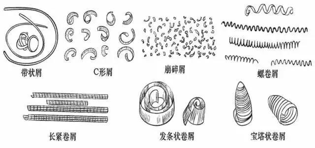
Classification of chip forms
Depending on the specific conditions of the room material, the geometric parameters of the tool and the use of the cut, the chip shapes generally include: the ribbon chips, the C -shaped chips, the collapse fleas , rollers, etc.
1. Band -shaped chips
When cutting metal materials into high -speed plastic metal, if the breast breaking measurements are not taken, the band -shaped fleas are very likely to form. Damage the sliced of the tool, or even damage the cutting edge of the tool.
However, it is sometimes desirable to obtain ribbon shavings so that the fleas can be released gently. For example, during boredom a blind hole on a vertical bore machine.
2. C-shape
During the transformation of general materials into carbon steel and alloy steel, C shavings are easily formed if a rotation tool with chip circuit breaker is used. C -shaped chips have no drawbacks of ribbon shavings. However, most C -shaped chips are broken by collision at the rear of the turn of the turn or the surface of the room. The high frequency of breaks and breaks can affect the softness of the cutting process, thus affecting the roughness of the transformed surface. Consequently, it is generally not desirable to obtain C rams in C during the finish. It is often hoped to obtain long screw fleas to make the cutting process relatively stable.

3. Balayage -shaped rolls
On heavy towers, use a deep and large power volume to turn the steel parts. . Consequently, the arc radius of the bottom of the chip disjunction groove is generally increased, so that the chips are broken in the shape of a spring and fall on the treatment surface and fall by their own weight.
4. Long tight rollers
The formation process of long tight roller chips is relatively stable and easy to clean.
5. Pagoda -shaped rolls
During CNC machining, machine tools or automatic wire processing, it is desirable to obtain this chip because these chips will not be wrapped around the tool and the room. It is also practical to clean.
6. Broken blows
When you transform brittle materials such as melting, fragile brass, flowing bronze, etc., the collapse of the needle or fragment type is very easy to form, which is easy to splash and damage people, and is easy to damage the machine tool. If rolling fleas are used, the chips can be connected in a short roller.
In short, the specific conditions for cutting treatment are different, and the forms of the chips that should be obtained are also different, but whatever the shape of the chips, the breaking of the fleas must be reliable.
2
Principle of flea rupture
During the metal cutting process, if the chips are subject to the rupture are directly linked to the deformation of the fleas.
The hardness of the shavings formed during the cutting process will be improved due to a relatively large plastic deformation, while plasticity and tenacity will be considerably reduced. After cold hardening, the chip becomes hard and brittle, and it is likely to break when it is subject to alternating flexion or impact loads. The greater the plastic deformation, the shavings undergo, the greater the hardness and fragility, and the easier it is to break. When cutting high resistance, high plastic and high toz materials which are difficult to break the shavings, it is necessary to increase the deformation of the chips to reduce its plasticity and its tenacity, in order to facilitate the purpose of the breaking of fleas.
The flea deformation can be made up of two parts:
The first part is formed during the cutting process, which we call the basic deformation. The deformation of the chip measured during the free cut with a flat front cut tool is relatively close to the basic deformation value. The main factors affecting the basic deformation include the front angle of the tool, the negative chamfer and the cutting speed. The smaller the front angle, the lower the negative chamfer, and the lower the cutting speed, the lower the deformation of the shavings, the more it is conducive to the breaking of the fleas. Consequently, the reduction of the front angle, the expansion of the negative chamfer and the reduction of the cutting speed can be used as measures to promote the breaking of the fleas.
The second part is the deformation that the chips undergo during flow and curling, which we call additional deformation. Because in most cases, only basic deformation during the cutting process cannot break the chips, additional deformation must be added to reach hardening and rupture. The easiest way to force chips to undergo additional deformation is to sharpen (or press) a certain form of chip circuit breaker on the surface of the front knife, and to force the chips to curl up and to deform when ‘They flow into the circuit breaker. Once the chip is subjected to additional curved deformation, it is still hardened and fate, and is easily broken when it strikes the room or surface of the rear blade.
3
Effect of the chip circuit breaker on the chip circuit breaker
The chip circuit breaker plays not only an additional role of deformation on the chip, but also has a significant impact on the shape of the chip and the break of the chip. In the cutting treatment, people use the different shapes and sizes of the chip circuit breaker and the angle of inclination between the chip circuit breaker and the main edge to control curling and breaking the chip. In order to better understand and master these rules, we will analyze in detail the shape, the size of the chip circuit breaker and the angle of inclination of the chip circuit breaker and the main edge of the shape of the chip and the breaking of the chips.
1. Form of the chip circuit breaker
The chip circuit breaker has three forms: type with linear arc, linear type and full arch type.

(1) A linear arch type circuit breaker is made up of a straight line and a circular arch. The right part forms the front of the tool, and the size of the radius of the RN arc at the bottom of the groove has a certain impact on curling and deformation of fleas. If Rn is small, the curling radius of the chip is small and the deformation of the chip is large; If RN is large, the curling radius of the chip is large and the deformation of the chip is small. At an average cutting depth (cutting depth AP = 2 ~ 6 mm), generally Rn = (0.4 ~ 0.7) B, B is the width of the chip circuit breaker.
(2) A linear chip circuit breaker is composed of two straight lines which cross, and its lower angle is 180 ° –σ (σ is called the corner angle of the chip disjunction table). replaces the arc RN The role of if the lower angle of the groove is small, the crimping radius of the chip is small and the deformation of the chip is large; At an average cutting depth, the corner angle of the flea rupture table is generally 60 ° to 70 °.

The two above-form chip circuit breakers are suitable for the treatment of carbon steel and alloy structure steel, with the front angle to γ. In the beach of 5 ~ 15 °.
(3) The main parameters of the fully arc chip disjunction groove are the width of groove B, the radius of the lower arc of the RN groove and the γ front angle. The relationship between them is:

Note: See Figure 5C

When cutting copper and stainless steel, any arc chip circuit breakers are often used. Because when processing highly plastic materials, the top angle of the tool is selected with a relatively large front angle (γ0 = 25 ° ~ 30 °), and the cutting edge of the groove tool Rupture of the arc chip is relatively strong and the groove is also shallow, which is practical for the flow, so it is more practical.
2. Width of the chip circuit breaker
The width of the groove of circuit breaker B is linked to the quantity of power f and to the depth of AP cutting. And the pace must be extended appropriately.

Fixed and unchanged, the effect of modifications of the width of the chip B circuit breaker on curling and deformation of the fleas. Figure 9a is essentially adapted to the width of the groove and the quantity of power. have a great deformation. To flow into the groove, which means that the fleas hold back and even damage the edge of the cut; Easy to break, and sometimes it does not even circulate through the bottom of the groove to freely form the ribbon shavings.
If the width of the circuit breaker is initially selected by the quantity of power, roughly, for cutting carbon steel, the relationship between width B and the quantity of power f is approximately B = 10F; necessary to increase the deformation of fleas, it can be desirable B = 7F.
Width B of the chip circuit breaker must also be adapted to the AP cutting depth. Generally, the width of the slit B can be coarsely selected on the basis of AP. Because when the cutting depth is large and the groove is too narrow, the chips are wide and not easy to complete in the groove. When the cutting depth is small and the groove is too wide, the shavings are narrow and the flow is relatively free and insufficient deformation and is not easy to break.
3. Angle of inclination between the chip circuit breaker and the main cutting edge
There are three inclination methods commonly used for the chip circuit breaker and the main edge: external oblique, parallel and inner oblique.

(1) External oblique type
The external oblique chip circuit breaker has a large front and a narrow back, and a shallow front and a shallow back.
The curling deformation of the circuit breaker of the external oblique chip is large. The curling radius is small and the deformation is large; To turn around on the surface of the reverse or the surface to be treated, and break after the collision to form a shaved in the shape of C.
This form of a chip circuit breaker. At an average cutting depth, the flea breaking range is wide, the breaking effect of fleas is stable and reliable, and it is widely used in production. The value of the tilt angle τ is mainly determined by the room material. taken.
However, when the cutting depth is large, because the width of the circuit breaker of the chip is too small near the circular surface external to the room (see Figure 11), the chips are subject to a blockage, and even the chips break The edge of the tip, so that the parallel type is generally used instead.
(2) Parallel type
The deformation of the chips of the parallel circuit breaker is not as large as that of the external oblique type, and most chips are broken on the treatment surface of the room.
During the cutting of carbon steel in shavings, the breaking effect of the chips of parallel rupture grooves is essentially the same as that of the external oblique type, but the supply must be slightly increased to increase the deformation of Additional curry curling.

(3) Inner oblique type
The interior oblique chip circuit breaker (see Figure 12) is the widest to the external circular surface has of the room and the narrowest at point B of the tool. Therefore, chips are often curled up in small rollers first at B, and in large rollers to A. When the tilt angle of the blade of the main cut edge is 3 ° ~ 5 °, the chips can Easily form continuous long and tight rollers. The inclination angle between the inner tilted circuit breaker and the main cut edge is generally τ = 8 ° ~ 10 °. That of the circuit breaker of the external tilted chip in production.
4
Several methods of breaking chips commonly used
1. Use circuit breakers
As mentioned earlier, flea breakers not only play an additional role in the deformation of fleas. It can also control the loop and breaking of fleas. As long as the shape, the size of the chip circuit breaker and the angle of inclination between the chip circuit breaker and the main cut edge are appropriate, the chip circuit breaker is reliable. Whether it is a welding tool or a clamp tool, a reproach tool or a non-scrubing tool can be used.

In order to apply different ranges of cutting dosages. The blades in cemented carbide are pressed with chip circuit breakers of different shapes and sizes, which are easy to choose, which is both economical and simple. This method is the preferred method in cutting and treatment and is also the most used method.
The drawback is that the determination of the reasonable geometric parameters of the tool is limited by the breaking requirements of the fleas.
2. Use circuit breakers
There are two types of circuit breakers: fixed and adjustable. Figure 13 shows an adjustable chip circuit breaker on the rotation tool.
A chip 1 barrier plate is installed at the front of the rotation tool. The LN and α parameters of the chip circuit breaker can be designed and adjusted if necessary to ensure that the breaking of the chips is stable and reliable in given cutting conditions. Loosen the screw 3, under the action of spring 4, the chip 1 stop plate 1 and the pressure plate 2 can be raised together, in order to facilitate the adjustment of the stop plate of the chip and indexation fast and replacement of the blade. This chip circuit breaker is often used on large and medium-sized machine tools.
3. Use the flea rupture device
There are many types of flea breaking devices, which can generally be divided into mechanical, hydraulic and electric types. Figure 14 is a schematic diagram of a flea breaking device with a cutting tool for filming. During the turn, the chips circulate through the Puce 2 guide channel and are forcibly cut by the 3 rotary disc cutter 3, and the cut chips are discharged from the discharge channel of the chip 6. The cutter is trained By the drive shaft 4. 1 in the figure is the rotation tool.
4. Method of the use of pre-Ruine on the surface of the part
Depending on the diameter of the room, one or more grooves are pre-opened along the axial direction of the room on the surface to be treated, and the depth is slightly smaller than the cutting depth, so that the cut chips form A low crossing -section and therefore break. This guarantees a reliable breaking of the fleas and does not affect the roughness of the surface treated in the room. Even during the treatment of materials with high tenacity, the breaking effect of fleas is very good. For example, when the fine drilling material (such as 40CR, etc.) has a strong tenacity in fine drilling, when it is difficult to break the shavings by other methods, longitudinal grooves can be drawn on the surface transformed then boring. This method can show its unique advantages.
5. Change the geometric parameters of the tool and adjust the use of the cut
From the principle of the chip mentioned above, we can see that the peak angle is reduced; The shape of the main slice is modified. However, taking these methods to cut fleas often brings harmful consequences, such as the decrease in productivity, the deterioration of the surface quality of the room and the increase in the cutting force. of fleas.
In addition, the use of the cutting fluid can reduce the plasticity and tenacity of the chips, and is also conducive to the breaking of the fleas. The increase in fluid pressure can better promote the breaking of fleas.
Daguang focuses on providing solutions such as precision CNC machining services (3-axis, 4-axis, 5-axis machining), CNC milling, 3D printing and rapid prototyping services.


