The control game of the peripheral movement of industrial robots mainly includes three parts: servo control, step control and frequency conversion control.
Control service
1. Principle of work of the AC Servomotor
The rotor inside the servomotor is a permanent magnet. The engine feedback signal is sent to the driver. The precision of the servomotor is determined by the precision of the encoder (number of lines).
2. Composition and classification of servomotes systems
composition:
The SERVO system is a general term for a control system with position and angle as a quantity of control. .
Classification:
1. According to the control structure, it is divided into: type in open loop and closed loop type.
2. According to the classification of driving components, it is divided into:
HAS.
B.
C.
3. Characteristics of the servomotor (AC)
1. High positioning precision, ordinary servomotors can reach 0.036 degrees
2. Quick response time.
3. Practical and flexible control, and easy to implement the control system.
4. There are many models, and different types can be selected depending on the different application environments.
5. Provide a complete closed loop control, which can monitor operating conditions in a timely time and provide appropriate adjustments and changes.
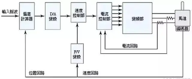
4. Structure of the servomotor system
5. Selection steps for servo control
1. Determine mechanical specifications, load, rigidity and other parameters.
2. Confirm the action parameters, travel speed, running, acceleration and deceleration time, period, precision, etc.
3. Select engine inertia, load inertia, engine conversion inertia and rotor inertia.
4. Select the engine rotation speed.
5. Select the nominal engine torque. Loading torque, acceleration and deceleration torque, instantaneous maximum torque, efficient torque.
6. Select the engine position resolution of the engine.
7. Select the engine model according to the above.
6. Application of servomotes control

Pas control
1. Principle of step -by -step engine work
A step -by -step engine is an actuator that converts electrical pulses into angular travel. When the step -by -step driver receives a pulse signal, he drives the engine step by step to run a fixed angle (called “angle of step”) in the adjustment direction, and his rotation works step by step at an angle fixed. The angular displacement can be controlled by controlling the number of impulses to achieve the objective of a specific positioning; Pas -by -step engines can be used as a special control engine.

2. Classification of steps
The most commonly used step -by -step engines now include reactive steps (VR), viing -to -permanent passing (PM), Step -by -Pas Passe Passe (HB) and Step -by -Monophase Stephanted Step .
● Passing engines with permanent magnet passages are generally two phases, with a small torque and a small volume, and the angle of step is generally 7.5 degrees or 15 degrees;
● The reactive step -by -step engine is generally three -phase, which can reach a large torque output. The magnetic routing of the rotor of the reactive steps is made of mild magnetic material, and there are multi-flat excitation windings on the stator, which generates the torque by changing magnetic permeability.
● The mixed step -by -step engine refers to the advantages of the permanent magnet mixture and reactive shapes. It is divided into two phases and five phases: the angle of steps with two phases is generally 1.8 degrees, and the angle of steps with five phases is generally 0.72 degrees. This step -by -step engine is the most widely used.
3. Step -by -step engine system

1. Static index terms for step -by -step engines
Phase number A. M. b.
c.
D.
E.
2. Dynamic indicators and step -by -step engine
HAS.
b. Call this a loss of steps.
c.
D.
E.
F. Race torque frequency frequency characteristics: The engine output torque curve and the frequency relationship during the operation measured by the engine under certain test conditions is called the frequency characteristics of the race torque.
4. Steeling of step by step
1. Selection of the PAS angle: The engine angle of the engine depends on the charging precision requirements.
2. Selection of the static moment: The static moment’s selection base is the load of the engine.
3. Current selection: Due to different current parameters, their operating characteristics vary considerably.

5. Some features of the steam engine
1. The accuracy of a step -by -step engine is generally 3 to 5% of the step -by -step angle and does not accumulate.
2. The maximum admissible temperature on the surface of the steps in step is generally greater than 130 degrees Celsius.
3. Pas -by -step engine torque will decrease with the increase in the rotation speed.
4. The engine step by step can operate normally at low speed, but it cannot start if it is greater than a certain speed, and it is accompanied by a whistling sound.
5. Step -by -step engines are used on low -speed occasions – the speed per minute does not exceed 1000 rpm.

6. Comparison of performance between two engines
1. Different control precision
The clip angle of the Hybrid Step to Pas Pas Pas Pas Pas Five Phases is generally 0.72 ° and 0.36 ° AC The control accuracy of the engine is guaranteed by the rotary encoder at the rear end of the tree engine. 360. ° / 10000 = 0.036 °, the servomotor has higher precision than that of the steps step by step.
2. Different low frequency characteristics
Step -by -step engines are subject to low -speed low -speed vibrations. The AC Servomotor works very well and does not even vibrate at low speed.


3. Different overload capacities
Pas -by -step engines generally do not have an overload capacity. The AC Servomotor has a strong overload capacity.
4. Different operational performance
Control of the step -by -step engine is controlling the open loop. The system is a closed loop control and the driver can the feedback signal of the motor coder is directly sampled, and the position ring and the speed cycle are formed inside. Control performance is more reliable.
5. Different speed response performance
It takes 200 to 400 milliseconds so that the engines step by step accelerate from the stationary at work speed (usually several hundred revolutions per minute). The acceleration performance of the AC Servocatry System is good. Start and stop.
6. Different torque frequency characteristics
Pas -by -step engine output torque is decreasing with the increase in rotation speed and will drop sharply at higher speeds.
To summarize, the SERVO AC systems are superior to step -by -step engines in many aspects of performance. However, on certain occasions when there are low requirements, step by step engines are often used as execution engines. Consequently, in the control system design process, we must in depth various factors such as control requirements and costs, and choose the appropriate control engines.

Frequency conversion control
1. Introduction to General Motors
The engine alternating with three -phase squirrel cage is the most common among induction motors.

Schematic diagram of the induction engine structure

Schematic engine diagram

2. Principles and composition of the frequency converter
A frequency converter is a control device that can simply change the rotation speed of an AC engine. The AC engine speed modification method is as follows.
The frequency converter performs speed regulation by modifying the power frequency of the AC engine:

The inverter is as follows:

1. Converter (rectifier)
A diode bridge rectifier is widely used, as shown in Figure 1, which converts the power supply of the power frequency to DC. Two sets of transistor converters can also be used to form a reversible converter.
2. flat waves circuit
The DC voltage rectified by the rectifier contains a pulsed voltage of 6 times the frequency of the power supply. In order to remove tension fluctuations, inductance and a capacitor are used to absorb pulsed voltage (current). The capacity of the device is small.
3. Inverter
Unlike the rectifier, the inverter converts the power CC into power CA of the required frequency and makes the 6 switching devices light at a determined time to obtain an AC output in three phases.
4. Braking circuit
When the asynchronous engine is used in the regenerative braking zone (the sliding rate is negative), the regenerative energy is stored in the capacitor of flat waves, which increases CC tension. In general, the energy accumulated by the inertia of inertia by the mechanical system (including the engine) is greater than the energy stored by the capacitor. The braking circuit (switch and resistance) to regenerate it.
3. Application objective and use of the frequency converter
The adjustable speed transmission formed by the inverter and the alternating current mechanism is called the inverter transmission, and its functions and uses are as follows. Among them, they can be linked to each other, but there is in fact no clear classification.

Daguang focuses on providing solutions such as precision CNC machining services (3-axis, 4-axis, 5-axis machining), CNC milling, 3D printing and rapid prototyping services.


