1 Preface
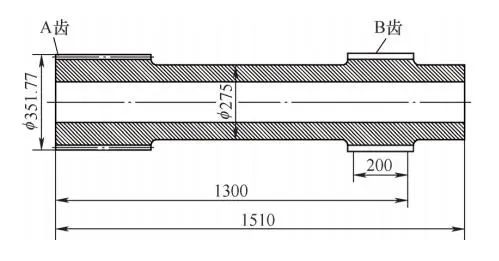
Figure 1 shows the outer structure and shape of the sun gear shaft drum. The total length of the sun gear shaft is 1510 mm. Special tooling with center holes is installed at both ends of the shaft due to processing requirements. The actual length is longer and exceeds the longitudinal clamping stroke of the vertical gear hobbing machine. the workbench is smaller than the outer circle of the left end teeth of the sun gear shaft, so it cannot be installed. At present, during the programming process of the modified horizontal gear hobbing machine, it is found that the maximum volume of the honing drum allowed to be gripped by the equipment is only a few thousand millimeters, which cannot meet the design requirements of drawing R33000mm. Outsourcing processing is expensive, and due to long-distance transportation, transportation costs increase and there are many potential risks such as dents and scratches during transportation. Since the product is produced in batches and in order to reduce costs and increase efficiency, technical research is carried out to achieve independent processing on existing gear cutting machines.
a)Structure

b) Fitting in the direction of the tooth to the external spline to the involute tooth B
Figure 1 The external structure and shape of the sun gear shaft drum
2 Drum spline processing principles
Drum groove processing is achieved by changing the radial cutting depth of the hob. For straight-toothed cylindrical drum splines, during the actual cutting process, the movement trajectory of the hob in the CNC system cannot grasp an arc radius greater than 5 digits, and cannot meet the pattern design requirements. According to the result of the infinite approximation of a circle by its inscribed polygon[1-3]it is planned to use differential arc and linear approximation methods to achieve this. The key now is determining the differential quantity and calculating the coordinate points. For a 200mm length spline plus the hob inlet and outlet distance, based on 300mm, how many straight lines should this arc be broken down into to meet the gear accuracy requirements ? It is initially determined that it is decomposed into 200 segments, that is, the Z value of each segment changes by 1.5 mm.
3 Calculation and programming of coordinate points
Depending on the workpiece structure and equipment requirements, relative coordinate programming is used when programming. The calculation of coordinate points (see Figure 2) uses relative coordinate points. The process of calculating coordinate points uses the Excel program.

Figure 2 Calculation of coordinate points
The program must be compiled by computer, making it easy to copy and paste coordinate points and avoiding manual entry of large amounts of data and entering incorrect data. The compiled program is imported into the processing equipment via the external USB transfer interface.
4 Trial production and sample testing
In order to verify the rationality and feasibility of this method, a piece of scrap metal was collected in the workshop and transformed into a splined shaft with the same number of teeth, different modules, the same length and the same drum shape as the part . The sample is shown in Figure 3.

a) Structure of the splined shaft

b) Adjustment in the direction of the external involute spline tooth
Figure 3 Sample
The processed sample is tested with a tooth detector. The test results are shown in Table 1, where Cβ is the shape quantity of the drum, Fβ is the total deviation of the spiral, fHβ is the tilt deviation of the spiral, and ffβ is the shape. deviation of the spiral. The drum shape quantity of 110 μm is less than the 150 μm required by pattern technology. The amount of drum shape on the left and right sides is uniform, but the spiral shape gap ffβ is large and the tooth shape wave is obvious.
Table 1 Examples of test results (unit: μm)

According to the test results in Table 1, the arc was decomposed into 400 segments, and the parts were tested after actual processing. The test results are shown in Table 2. The drum shape quantity of 130 μm is closer to the 150 μm required by. pattern technology. The drum shape uprights on the left and right sides are uniform and spiral. The linear shape deviation ffβ is significantly reduced, and the wavy transition from tooth to shape is smoother.
Table 2 Part inspection results (unit: μm)

5Conclusion
Verified by product processing, this technological innovation has exceeded the limit of the arc radius of the CNC programming system and completed the batch processing of large drum-shaped splines for ultra-long solar gear shafts of the wind energy. It not only met the design requirements, but also saved money. manufacturing costs. At the same time, he obtained the following conclusions.
1) On horizontal gear hobbing machines, the programming and processing problems of large drum-shaped splines can be solved by applying the linear approximation method to arcs.
2) When the axial arc distance of the large differential drum is divided with an accuracy of 0.75mm, it can meet the precision requirements of gear manufacturing.
Daguang focuses on providing solutions such as precision CNC machining services (3-axis, 4-axis, 5-axis machining), CNC milling, 3D printing and rapid prototyping services.


