In the precision manufacturing industry, the question of “Which software to use with a CNC machine?” is as fundamental as asking a master craftsman about their favorite tools. The choice of software directly impacts every stage of the production cycle, from initial design to the final part validation. For a professional partner like GreatLight CNC Machining Factory, the software ecosystem is the digital backbone that translates intricate client ideas into tangible, high-precision components. This guide will navigate through the essential software categories, providing insights to help you make informed decisions for your projects.
The Software Trinity: CAD, CAM, and CNC Control
A seamless CNC machining workflow is built upon three pillars of software: Computer-Aided Design (CAD), Computer-Aided Manufacturing (CAM), and the Machine Control Software (often CNC or G-Code specific). Understanding their distinct roles is crucial.

H3: 1. Computer-Aided Design (CAD) Software: Where Ideas Take Shape
CAD software is used to create the detailed 2D or 3D digital model (the “blueprint”) of the part. This model defines the geometry, dimensions, and tolerances. The choice here depends on industry, complexity, and collaboration needs.
For General Mechanical & Product Design:
SolidWorks: A industry-standard for parametric 3D modeling. Its intuitive interface, powerful assembly management, and extensive ecosystem make it a top choice for mechanical engineers and product designers.
Autodesk Inventor: Similar to SolidWorks, it excels in product simulation, tooling design, and is deeply integrated with other Autodesk manufacturing solutions.
Siemens NX: A high-end solution favored in aerospace, automotive, and complex machinery. It offers unparalleled capabilities for freeform surface modeling and integrated CAD/CAM/CAE (Computer-Aided Engineering).
PTC Creo: Known for its robust parametric and direct modeling capabilities, ideal for organizations with complex, evolving product lines.
For Complex Surfacing & Aesthetic Design:
Dassault Systèmes CATIA: The gold standard for complex surface modeling, widely used in automotive (Class-A surfaces) and aerospace industries. Its capability to handle extremely large assemblies is legendary.
Autodesk Alias: Specializes in industrial design and Class-A surface creation, often used in tandem with engineering-focused CAD software.
At facilities like GreatLight CNC Machining Factory, we are fluent in all major CAD formats (STEP, IGES, SLDPRT, X_T, etc.). Our engineers can work directly with your native CAD files, which streamlines communication and eliminates data translation errors that can occur with neutral formats.

H3: 2. Computer-Aided Manufacturing (CAM) Software: The Strategic Planner
CAM software is the critical bridge between the CAD model and the CNC machine. It takes the 3D geometry and generates the toolpaths—the precise instructions (G-code) that tell the machine tool where to move, how fast to spin, and how deep to cut. This is where manufacturing expertise is digitally encoded.
Integrated CAM Suites:
Siemens NX CAM / SolidWorks CAM: These offer tight integration with their respective CAD environments, allowing for a streamlined design-to-manufacturing workflow within a single platform. Changes in the CAD model can automatically update the toolpaths.
Fusion 360 (by Autodesk): A cloud-based, integrated CAD/CAM/CAE platform that has gained immense popularity for its accessibility, affordability, and powerful toolpath strategies for milling, turning, and additive manufacturing.
Best-in-Class Standalone CAM:
Mastercam: One of the most widely used standalone CAM systems globally. It is renowned for its reliability, vast post-processor library (for any machine), and powerful strategies for 2D, 3D, multi-axis, and mill-turn machining.
ESPRIT: Known as “the CNC programming language,” it excels in dynamic machining for mills, lathes, and multi-tasking mill-turn centers. Its strength lies in true knowledge-based machining and efficient code generation.
HyperMILL (by OPEN MIND): A premium solution, particularly dominant in the realm of 5-axis CNC machining and impeller/blisk machining. Its advanced algorithms maximize material removal rates while ensuring superior surface finishes and tool life.
For a factory equipped with advanced five-axis CNC machining centers like ours, the CAM software’s ability to handle simultaneous 5-axis toolpaths, collision avoidance, and complex surface finishing is non-negotiable. We leverage high-end CAM software to unlock the full potential of our machinery, tackling geometries that are impossible with 3-axis setups.
H3: 3. CNC Machine Control & Simulation Software: The Virtual Dry Run
Before any metal is cut, the generated G-code must be verified.
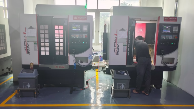
CNC Simulators (e.g., Vericut, NC Simul): These create a virtual replica of the actual CNC machine, tools, and fixtures. They simulate the entire machining process to detect programming errors, collisions, and inefficient tool movements. This virtual validation is a cornerstone of our quality assurance at GreatLight CNC Machining Factory, preventing costly mistakes and ensuring first-part correctness.
Machine-Specific Control Software: Each CNC machine brand (e.g., Siemens SINUMERIK, Heidenhain, FANUC, Haas) has its own proprietary control system with a unique interface and G-code dialect. Our skilled machinists are proficient in these controls, allowing for on-the-fly optimizations and fine-tuning at the machine level.
H2: Beyond the Core: Supplementary Software for a Robust Workflow
Metrology & Inspection Software (e.g., PC-DMIS, GOM Inspect): Used to program CMMs (Coordinate Measuring Machines) and analyze scan data to verify that machined parts conform to the CAD model and specified tolerances. This is integral to our in-house quality control, ensuring every part meets the promised precision of ±0.001mm.
ERP/MRP & Production Management Software: Systems that manage quoting, order tracking, inventory, scheduling, and overall shop floor operations. This digital management backbone is what enables us to handle complex, high-mix, low-volume production runs efficiently and deliver on tight timelines.
H2: Making the Right Choice: Factors to Consider
Part Complexity: Simple 2.5D parts may only need basic CAM, while complex freeform surfaces demand high-end 5-axis CAM capabilities.
Industry Standards: Aerospace and automotive often mandate specific software (e.g., CATIA, NX) for data exchange.
Collaboration Needs: If you are designing in SolidWorks, using SolidWorks CAM or a partner with deep expertise in that ecosystem (like GreatLight Metal) can drastically reduce friction.
Budget & Scale: Integrated platforms like Fusion 360 are excellent for startups, while large enterprises invest in suites like NX or CATIA for their enterprise-wide capabilities.
Your Manufacturing Partner’s Expertise: Ultimately, one of the most significant software decisions is choosing a manufacturing partner with the right software stack and, more importantly, the engineering knowledge to wield it effectively. A partner with ISO 9001:2015 and IATF 16949 certifications demonstrates a systematic approach to managing this entire digital workflow.
Conclusion: Software as a Partnership Enabler
The question of “which software to use with a CNC machine” doesn’t have a single answer. It’s about building a coherent digital thread from design to delivery. For our clients, the most important software choice is often the implicit one: selecting a manufacturing partner whose software proficiency and technological infrastructure are aligned with their project’s demands.
At GreatLight CNC Machining Factory, we view our advanced software suite—from high-end CAD/CAM to precise simulation and metrology tools—not as a cost, but as an investment in predictable, high-quality outcomes. This digital expertise, combined with our physical arsenal of five-axis CNC machining centers and rigorous quality systems, allows us to serve as a true extension of your engineering team, transforming complex designs into flawless precision parts.
Frequently Asked Questions (FAQ)
Q1: Can I just send you a 2D drawing, or do I need a 3D CAD model?
A: While we can work from detailed 2D drawings, a 3D CAD model (in STEP, IGES, or native format) is highly recommended and often essential for complex parts. It eliminates ambiguity, allows for automatic toolpath generation, and enables advanced simulation, leading to faster turnaround and reduced risk of errors.
Q2: My designer uses Software A, but I heard your CAM works best with Software B. Will this be a problem?
A: Not at all. Professional manufacturers like us are equipped to handle data from all major CAD platforms. We use robust data translators and have experience working with various native file formats. The key is to communicate early about your file format so we can ensure a smooth transition into our CAM system.
Q3: What is the role of a “post-processor” in CAM software, and why is it important?
A: A post-processor is a translator that converts the generic toolpaths from the CAM system into specific G-code that your particular brand and model of CNC machine can understand. Having a correctly configured, optimized post-processor is critical for safety, efficiency, and leveraging the unique features of a machine. We maintain a library of certified post-processors for all our equipment.
Q4: For a startup with a limited budget, what is the most cost-effective software path for preparing files for CNC machining?
A: Consider using a capable, affordable (or free for personal use) CAD modeler like Fusion 360, Onshape, or FreeCAD for design. For manufacturing, you can partner with a supplier like GreatLight CNC Machining Factory that has the professional CAM software and expertise. You provide the validated 3D model, and we handle the complex, equipment-specific CAM programming as part of our service, saving you the high cost of purchasing and learning advanced CAM software.
Q5: How does your software and simulation process help guarantee the high precision you claim (±0.001mm)?
A: Precision is a result of the entire chain. Our CAM software allows us to program optimal toolpaths that minimize stress and deflection. Simulation software then verifies the code is collision-free and will produce the intended geometry. Finally, our machinists use the machine control software to fine-tune parameters, and metrology software validates the final part against the original CAD model. This closed-loop digital-physical process, governed by our ISO-certified systems, ensures consistent, verifiable precision. For more insights into our technical capabilities and industry engagements, you can follow our professional updates on platforms like LinkedIn.


