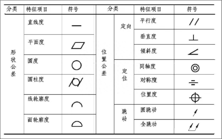
Geometric tolerance is also generally called geometric tolerance, including shape tolerance and position tolerance.
Shape tolerances include: straightness, flatness, roundness, cylindricity, line profile and surface profile;
Orientation position tolerances include: parallelism, perpendicular and tilt;
Positioning position tolerances include: coaxiality, symmetry and position;
Runout tolerance includes: circular runout and total runout.
Some of these tolerances are single tolerances and others are global tolerances. Although the concepts are different, they are closely related.
Correctly marking geometric tolerances on drawings is very important to meet part design, manufacturing and inspection requirements. Therefore, it is necessary to have a thorough understanding of the relationship between shape and position tolerances and how to mark geometric tolerances.
1. Selecting geometric tolerance
In order to meet the functional requirements, simple measuring elements should be selected to take full advantage of the geometric tolerance control capability to reduce the geometric tolerance elements and inspection elements shown on the drawings.
For example, the coaxiality tolerance is often replaced by a radial circular runout tolerance or a full radial runout tolerance. However, it should be noted that circular runout is a combination of coaxiality error and cylindrical surface shape error. Therefore, when replacing, the given runout tolerance value should be slightly higher than the coaxiality tolerance value, otherwise the requirements will be too strict.
2. Selection of tolerance principles
Tolerance principles stipulate the relationship between dimensional tolerances and geometric tolerances. According to the functional requirements of the measured elements, the capabilities of geometric tolerance and dimensional tolerance should be fully utilized, and appropriate tolerance principles should be adopted.
The independence principle is used in situations where the accuracy requirements for dimensional accuracy and shape accuracy are very different and the requirements must be met separately. There is no correlation between the two, ensuring movement precision, watertightness and no tolerances.
The inclusion requirement is mainly used in situations where the corresponding properties must be strictly guaranteed.
The maximum entity requirement is used for core elements and is typically used when accessories require assembly (no corresponding property requirements). The “Mechanical Engineering Literature” public account, a service station for engineers!
Minimum feature requirements are mainly used in situations where part strength and minimum wall thickness must be guaranteed.
The combination of reversible requirements and maximum or minimum feature requirements can make full use of the tolerance zone, expand the actual size range of measured elements, improve efficiency, and can be selected without affecting performance.


3. Selection of reference elements
01 Selection of reference parts
(1) Select the parting surface where the parts are positioned in the machine as the reference position.
For example, the bottom plane and sides of the box, the axis of disc parts, the supporting journal or the supporting hole of rotating parts, etc.
(2) Reference elements must be of sufficient size and rigidity to ensure stable and reliable positioning.
For example, using two or more axes further apart to form a common reference axis is more stable than a single reference axis.
(3) Select a more precisely processed surface as the reference part.
(4) Try to unify assembly, processing and testing standards.
In this way, errors caused by inconsistent references can be eliminated; the design and manufacturing of fixtures and measuring tools can also be simplified, making measurement more practical.
02. Determination of the reference quantity
Generally speaking, the number of references must be determined according to the geometric functional orientation and positioning requirements of the tolerance project. Most orientation tolerances require a single datum, while positioning tolerances require one or more datums. For example, for parallelism, perpendicularity and coaxiality tolerance elements, usually a single plane or axis is used as a reference element for position tolerance elements, if the position accuracy of the hole system needs to be determined, two or three elements can be used. be used as a reference element.
03. Layout of the reference sequence
When more than two reference elements are selected, the order of the reference elements must be clear and written in the tolerance box in the order of first, second and third. The first reference element is the main one, followed by the second reference element. .

4. Determination of geometric tolerance values
The general principle: select the most economical tolerance value while satisfying the function of the part.
At the same time, depending on the functional requirements of the parts, taking into account the processing economy as well as the structure and rigidity of the parts, the tolerance values of the elements are determined according to the table. And consider the following factors:
(1) The shape tolerance given by the same element must be less than the position tolerance value;
(2) The shape tolerance value of cylindrical parts (except the straightness of the axis) should be less than its dimensional tolerance value, because on the same plane, the flatness tolerance value should be less to the parallelism tolerance value of the plan to be achieved; the data. The “Mechanical Engineering Literature” public account, a service station for engineers!
(3) The parallelism tolerance value must be less than its corresponding distance tolerance value.
(4) Approximate proportional relationship between surface roughness and shape tolerance: generally in the case of medium precision (level 7, 8, 9), the Ra value of surface roughness can be taken like 1/10~1/5 of the shape tolerance. value.
(5) For the following situations, considering the processing difficulty and the influence of other factors other than the main parameters, and while meeting the functional requirements of the part, appropriately reduce the selection from 1 to 2 levels:
has. The hole is relative to the axis;
b. Shafts and holes with greater slenderness; trees and holes with greater distances;
c. Surface area of larger width parts (greater than half the length);
d. Parallelism and perpendicular tolerances line to line and line to line compared to face to face.

5. Not specifying requirements for geometric tolerances
In order to simplify the drawing, it is not necessary to indicate the geometric tolerance on the drawing for the geometric accuracy that can be guaranteed by the general processing of the machine tool. Geometric tolerance not shown shall be implemented in accordance with the provisions of GB/T 1184. -1996. The general content is as follows:
(1) Three tolerance levels H, K and L are specified for unspecified straightness, flatness, verticality, symmetry and circular runout.
(2) The non-injected circularity tolerance value is equal to the diameter tolerance value, but cannot be greater than the non-injected radial circular runout tolerance value.
(3) The unspecified cylindricity tolerance value is not specified and is controlled by the injected or unspecified tolerances of the element roundness tolerance, main line straightness and relative line parallelism main.
(4) The unnoted parallelism tolerance value is equal to the largest of the unnoted tolerance values of the dimensional tolerance between the measured element and the reference element and the shape tolerance (straightness or flatness) of the element measured, and takes both. elements is used as a reference.
(5) The coaxiality tolerance value is not specified and is not specified. If necessary, the unindicated coaxiality tolerance value can be equal to the uninjected circular runout tolerance.
(6) The tolerance values of the uninjected line profile, surface profile, inclination and position are controlled by the injected or uninjected linear dimensional tolerance or angular tolerance of each element.
(7) The total runout tolerance value is not specified and is not specified.

6. Annotations on drawings where shape and position are not noted and tolerance values are not noted
If the unspecified tolerance value specified in GB/T 1184-1996 is used, the quality standard and code should be noted in the title column or technical requirements.
For example: “Geometric tolerance values not shown comply with GB/T1184-K.”
Daguang focuses on providing solutions such as precision CNC machining services (3-axis, 4-axis, 5-axis machining), CNC milling, 3D printing and rapid prototyping services.


