Aiming at the difficulties of processing thin-walled titanium alloy parts with high aspect ratio and the shortcomings of traditional processing methods, CNC longitudinal cutting process analysis was used to reduce the deformation caused by resistance to cutting parts A. The feeding tool was designed to solve the problem of fine turning of the outer circle. Regarding the clamping problem, the alignment tooling is designed to solve the deformation problem after turning is completed. Through equipment optimization, process plan improvement, processing parameter adjustment, deformation correction and other measures, a set of reasonable processing processes have been explored and verified , and the difficulties of processing thin-walled parts have been overcome.
01
Preface
Titanium alloy materials are increasingly used in the aerospace field due to their excellent properties such as high strength, low density, corrosion resistance, high temperature resistance and good weldability. Titanium alloy materials are typical materials that are difficult to machine. They have poor thermal conductivity during processing, high viscosity and low elastic modulus during cutting. Parts are subject to significant deformation and distortion, and processing accuracy is difficult to guarantee. During machining, those whose wall thickness is <1 mm sont des pièces à paroi mince et celles dont le rapport d'aspect est >10 are thin shaft parts that have low rigidity, are difficult to clamp, and are prone to machining deformation due to the influence of cutting. strengths.[1]。
The main difficulties in processing thin-walled titanium alloy parts with high aspect ratios are poor heat dissipation, poor rigidity and low bending strength. During the processing process, they are affected by cutting force, cutting heat and other factors, which easily cause such problems. such as bending, taper defects and belt drum shapes. To this end, these processing problems can be solved through equipment optimization, process plan improvement, processing parameter adjustment, deformation correction and other measures.
02
Part structure and processing requirements
The material of a certain part is TC6-M titanium alloy (double annealed). The dimensions of the part are shown in Figure 1. The aspect ratio is close to 40, and the wall thickness is less than 0.5 mm. walled structure with a large aspect ratio. The inner hole is φ (4.6 ± 0.05) mm, the total length is (186 ± 0.2) mm, and the surface roughness value Ra = 3.2 μm. The outer circle of the big end is φ8mm and the size is strict; the outer circle of the small end is φ5.4mm, and the straightness requirement is 0.1mm.
2.1 Material analysis
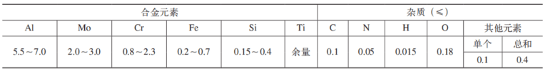
TC6 titanium alloy is an α-β martensitic two-phase titanium alloy with good comprehensive properties. Its nominal composition is Ti-6Al-2.5Mo-1.5Cr-0.5Fe-0.3Si, which has high strength at room temperature. The chemical composition is shown in Table 1.[2]can work for a long time below 400℃ for more than 6000h and below 450℃ for 2000h.
Table 1 Chemical composition of TC6 titanium alloy (mass fraction) (%)
2.2 Analysis of processing difficulties
The parts have a simple structure and high requirements for dimensional accuracy. Clamping force and radial cutting force can easily deform parts, making clamping difficult. The poor cutting processability of titanium alloy materials also increases the difficulty of designing the processing plan.
Parts with high aspect ratios are typically processed using chuck clamping and rotary center clamping. Generally, tool holders and center supports should be installed to balance radial cutting forces and reduce workpiece deformation during processing.[3]. The parts shown in Figure 1 are limited by the dimensions of the outer circle and length and cannot be directly clamped by the center frame and tool holder. Therefore, improving the clamping rigidity of parts and reducing bending deformation are the main measures to ensure dimensional accuracy. parts.

Figure 1 Room size
03
Processing technology
3.1 Process plan design
1) A margin of 10mm is reserved in the axial direction of the workpiece as an additional process amount for clamping to reduce the impact of the clamping force on the dimensional accuracy of the outer circle of the clamping workpiece.
2) Leave a margin of 0.2mm for the outer circle of φ8mm and 2mm for the outer circle of φ5.4mm during CNC turning to improve the clamping rigidity of the workpiece during the drilling process deep holes. The outer rotated circle serves as a positioning reference. the process of deep hole drilling. The inner hole is drilled using a high-precision PT2/750 deep drill to ensure the tolerance of the hole diameter.
3) When finishing the outer circle by CNC turning, use the inner hole to position the through chuck to increase the rigidity of the workpiece and reduce bending deformation. This process is the most difficult to deal with.
4) When the parts are processed to the final wall thickness, in order to reduce the deformation caused by cutting off the extra quantity, EDM wire cutting is used to remove the extra quantity from the process, the installer processes the R0.2mm fillet, and the end face is polished, and the electrical corrosion caused by electrical machining is removed in layers.
3.2 Treatment process
Process flow: material preparation → CNC turning → deep hole drilling → CNC precision turning → wire cutting → fitting → ultrasonic cleaning → fluorescence defect detection → inspection → anti-rust storage.
Use φ15mm × 200mm titanium alloy bar, CNC lathe turns the outer circle to φ10mm × 198mm, process the deep hole drilling positioning reference, drill the hole of φ (4.6 ± 0 .05) mm in one step and use the inner hole to position the CNC. accurately turning the outer circle, and finally use wire cutter to remove the extra quantity, and the installer cleans the parts after deburring, then delivers them to the warehouse for inspection.
04
Problems and analysis in treatment
4.1 Problems
When CNC precision turning the outer circle after deep drilling, penetration problems arise due to excessive dimensions and coaxiality of the outer circle.
(1) Method 1 of fine turning of the outer circle ① 5 steps: Rough turning of the outer circle with two heads. The process parameters are speed n=800r/min, feed f=0.14mm/r and shrinkage tolerance 0.2mm. ②10 working steps: adopt clamping method and top method (self-made cap), process parameters are approximate rotation speed n=800rpm, feed quantity f=0.14mm /r, a cut at φ5.56 mm, a shrinkage margin of 2 mm; fine turning Turning speed n=800r/min, feed f=0.1mm/r, cutting at φ5.36mm.
After turning, the outer circle of the part deforms the tool and takes the shape of a drum (see Figure 2). The average measured part size is φ5.8mm and both ends are φ5.5mm; the surface roughness value of the outer circle is Ra>6.3 μm;

Figure 2 Deformation of the part
(2) Method 2 of finishing the outer circle improves the trajectory of the finishing turning tool by checking the deformation and position of the outer circle, according to the deflection value of 0.3mm (φ5.8mm -φ5.5 mm) in the direction of the diameter. program from one end of the room to the middle. The position is inclined to compensate for the phenomenon of knife yield. The penetration of the inner hole after processing the workpiece is shown in Figure 3.

Figure 3 Penetration of the inner hole of the part
4.2 Problem analysis
(1) Analysis of reasons The main reason why the shape of the outer circle of the workpiece is drum-shaped is that when turning the workpieces on a CNC lathe, the workpieces are clamped using a clamping method on top. The parts have a long overhang and. poor rigidity. The cutting force during turning can be decomposed into axial cutting force, tangential cutting force and radial cutting force. The axial cutting force and the tangential cutting force cause slight longitudinal deformation of the workpiece and have little effect on the workpiece and the radial cutting force; The axis of the workpiece is vertical, which causes the workpiece to bend and deform, resulting in the smallest amount of cutting in the middle of the workpiece, and the workpiece becomes the shape of a waist drum after the treatment.
Penetration of the inner hole of the workpiece is mainly caused by the excessive coaxiality between the inner hole and the outer circle of the workpiece. After drilling the inner hole deep, the part was bent and deformed. has no straightness requirement for the outer circle. After drilling, the inner hole and the outer circle are not axial, and the cutting tolerances when rotating the outer circle on the two vertices are different, resulting in local penetration.
(2) Analysis of the mechanism: the parts are clamped using pliers and a top. The total length of the piece is 186 mm. When the CNC lathe turns the outer circle, the overhang is longer. affected by the radial cutting force and the length of the overhang, resulting in bending deformation. The mechanical model of outer circle turning by CNC lathe is shown in Figure 4.

Figure 4 Mechanical model of outer circle turning
According to the mechanics of materials, when rotating the outer circle, the formula for calculating the amount of deformation δ at the end of the workpiece is:
δ=64FL3/(3πEd4) (1)
In the formula, δ is the strain (mm); F is the radial cutting force of the tool acting on the workpiece (N) is the length of the overhang, which refers to the distance between the workpiece clamping point and the action point of the workpiece ‘tool ; (mm); E is the elastic modulus of the part material (N/mm2); d is the diameter of the workpiece blank (mm). It can be seen from equation (1) that when the workpiece material and the workpiece diameter are constant, the factor that has the greatest influence on the turning deformation δ of the workpiece is the length of the door to turn. false L, followed by the radial cutting force F.[4]。
05
Improvement of processing technology
5.1 Equipment optimization
Processing characteristics of CNC slitting lathe: The spring-loaded chuck in the spindle clamps the bar material for rotation and axial feed movement, and the tool moves radially. Since the movement path of the tool is perpendicular to the workpiece axis, that is, the workpiece rotates and moves during turning, the turning tool does not need to follow the movement of the part and the cutting tool always remains at the clamping level. position between the spindle and the workpiece, so that the parts The processing workpiece is always in a position with good rigidity. As the overhang length L becomes smaller as the workpiece turning tool moves, the deformation δ decreases exponentially. more suitable for processing parts with a high aspect ratio.
Slitting lathes are fundamentally different from conventional lathes. Conventional lathes rely on tool movement to turn excess blanks during processing. For precision thin shaft parts, conventional lathes are obviously unable to meet the processing needs. The length/diameter ratio of this part is close to 40, so it is more suitable to process it on a CNC slitting lathe. When processing parts with slitting equipment, an additional length of the feed part should be left (> 200 mm). When processing this part with a conventional lathe, the additional process length only requires 15 mm.
Since the workpiece material is TC6 titanium alloy, which is expensive, much of the extra process length is reserved for processing the parts on the slitting lathe. The process cost is too high, and the products being processed have been deeply processed. The process of drilling holes of parts on site cannot be processed. Therefore, in order to solve the clamping problem when processing on a slitting lathe while maintaining the same workpiece preparation length, the following measures are mainly taken.
1) The additional position of the workpiece is processed with M5 × 0.5-6H internal thread, and the screw length is 9mm.
2) Design the feed rod (see Figure 5) to replace the process accessory. The material of the power rod is 45 steel, 240mm long with M5×0.5-6h external thread. The outer diameter of the feed rod should be the same as the outer diameter of the workpiece before slitting. The spring-loaded chuck is reliable for tightening.

a)Dimensions

b) Physical objects
Figure 5 Food cane
3) In order to improve the rigidity of the workpiece, the outer diameter of the feed rod is based on the nominal outer diameter of the workpiece 8.5mm (lathe spring chuck specifications φ8.5mm), and dimensional tolerance is divided into 1 group. every 0.02 mm, for a total of 5 groups.
5.2 Adjust cutting parameters
TC6 titanium alloy material has poor thermal conductivity, high material viscosity and low elastic modulus during cutting, and the workpiece is prone to significant deformation. When cutting titanium alloys, the cutting temperature is high in the area near the cutting edge, and the titanium element is very active and prone to chemical reactions with oxygen, exacerbating tip wear of the tool. Through comparative experiments on several brands of blades, the tools and cutting parameters for CNC slitting lathe processing of TC6 titanium alloy materials were used for turning, the cutting parameters were speed n = 900 rpm; , feed The quantity f = 0.02 mm/r. After processing, the parts can meet the surface roughness value Ra=1.6 μm and the outer circle straightness of 0.3 mm, but cannot meet the outer circle straightness of 0.1 mm. At the same time, it is difficult to guarantee the coaxiality of the interior. hole towards the outer circle φ0.2 mm.
5.3 Optimize the process plan
(1) The deformation and straightening process is a processing method to eliminate the radial bending of shafts, rods and pipe parts.[5]. The parts have been bent and deformed after deep drilling, and additional straightening process is required. After drilling a deep hole, the wall thickness of the outer circle is >2mm, and the installer uses pressure point straightening, and the straightness of the workpiece is ≤0.15mm.
Since the straightness of the outer circle after slitting is 0.3mm, which cannot meet the coaxiality requirements of the drawing, it is necessary to straighten the finished outer circle by φ5.4mm. At this point, the wall thickness of the part is only 0.4mm. , and it is directly pressed against the outer circle of the workpiece. Surface alignment can easily cause surface deformation of parts. For this purpose, the alignment device is designed as shown in Figure 6, using pressure point alignment. The parts are placed on the device with a double V-shaped structure for position limitation, and the pressure head is designed as a bronze semi-circular ring shape. . Bronze material is softer than titanium alloy. The pressure head is replaced by a toroid to increase the contact area. Before straightening, first check the straightness of the outer circle and mark the bending point with a red pen. Then straighten and visually check that there is. There is no pressure on the outer circle of the part. Check that the outer circle, inner hole diameter and coaxiality of the part meet the requirements of the design drawing.

Figure 6 Alignment device
(2) The outer circle of fine turning and cutting process is also applied to the φ8 big end![]() The outer circle of mm is finely machined, the shrinkage process is added and the R0.2mm polishing is completed, and the sharp edge is retained on the large end surface. First use the machining center tool holder for clamping, and use the arc-shaped spring chuck to clamp the workpiece close to the outer circle of the cylindrical head. Increasing the contact area can reduce the clamping deformation, then tighten the tool holder. the CNC lathe to customize On the central chuck (see Figure 7), use a CNC lathe to finely turn the big end φ8
The outer circle of mm is finely machined, the shrinkage process is added and the R0.2mm polishing is completed, and the sharp edge is retained on the large end surface. First use the machining center tool holder for clamping, and use the arc-shaped spring chuck to clamp the workpiece close to the outer circle of the cylindrical head. Increasing the contact area can reduce the clamping deformation, then tighten the tool holder. the CNC lathe to customize On the central chuck (see Figure 7), use a CNC lathe to finely turn the big end φ8![]() mm outer circle, and remove the extra process to ensure the full length of the workpiece, polish the left end face of the workpiece to R0.2mm and keep the sharp edge.
mm outer circle, and remove the extra process to ensure the full length of the workpiece, polish the left end face of the workpiece to R0.2mm and keep the sharp edge.

Figure 7 Outer circle clamping method for fine turning
5.4 Improved process flow and treatment effect
The content of the part preparation and CNC turning rough machining processes remains unchanged. The deep hole drilling process is divided into roughing and finishing. The hole diameter is controlled according to φ (4.6 ± 0.05) mm. of 0.15 mm. The CNC turning process is added – — Turn the outer circle to φ8.5mm, process the internal thread in the extra length of the workpiece, and install the feed rod. A CNC slitting lathe is used to finish the outer circle of φ5.4mm. After slitting, the parts are straightened to a straightness of 0.1 mm. Finally, a CNC lathe is used to remove the outer circle. The cleaned parts are subject to non-destructive testing before delivery to the warehouse.
The improved process flow: material preparation → CNC turning → deep hole drilling → straightening → CNC turning → longitudinal cutting → straightening → CNC turning → ultrasonic cleaning → fluorescent flaw detection → inspection → anti-rust storage. A total of 60 parts were processed in 2 batches according to the improved process plan, and 59 parts were qualified. Parts have been assembled and verified to meet product performance requirements.
06
Conclusion
This paper aims at the difficulties of processing thin-walled titanium alloy parts with high aspect ratio, and explores a set of reasonable process flows through equipment optimization, process improvement, adjustment cutting parameters, warping correction and other improvement measures. The key to processing is to improve the rigidity of parts and solve the problems of part deformation. For parts that cannot be clamped using a center frame, CNC slitting equipment can be used to process them to improve the deformation problem caused by cutting forces during traditional part processing . Due to the high material cost of titanium alloy parts, in order to reduce the additional length of the CNC longitudinal cutting process, special feeding tools can be designed, titanium alloy material cutting tools and parameters cutting blades can be used universally with parts of the same material; and good rigidity, and the process parameters should vary depending on the equipment and parts. The specific structure must be adjusted appropriately; the straightening process can improve the deformation of thin walls with high aspect ratios. During straightening, the tooling uses internal annular pressure. head to increase the contact area, which solves the problem of local size deviations or appearance damage of parts.
Daguang focuses on providing solutions such as precision CNC machining services (3-axis, 4-axis, 5-axis machining), CNC milling, 3D printing and rapid prototyping services.


