01
Preface
Aluminum alloy thin plate parts are common parts in chassis parts. It has always been difficult to control processing deformation and ensure thickness consistency. In particular, T4 and T6 states have high hardness and are easy to deform. , it is extremely difficult to ensure consistency in the thickness and surface quality of the part. This article summarizes the causes of deformation and the processing experience of thin plates and special-shaped thin plate parts in several stages, and discusses the processing techniques of vacuum cupping.
02
Processing skills
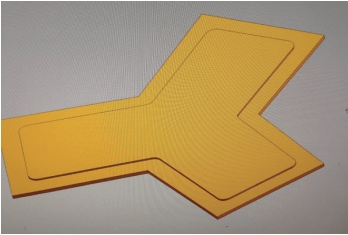
Figure 1 is a simplified model of a cover plate part. This is a rotationally symmetrical center piece with a rotation angle of 120°. There is a 1mm boss on one side and a 2mm groove on the other side. 2.5mm. In combination with the exterior dimensions of the part, it is determined that the part is a thin plate part. The workpiece material is T4 hard aluminum alloy, which is very easy to deform and can easily cause uneven thickness and size during processing.
a) Before

b) back
Figure 1 Simplified model of a certain cover plate part
03
Analysis of part deformation
The traditional processing method uses the micro-stress clamping method of bonding and AB glue fixation, or the local processing method of inverted plate areas. Among them, the adhesive method may cause the workpiece to bulge and thin due to deformation, and because the central bulging part has no supporting force, it will cause processing vibration and affect the surface quality, it is therefore not suitable for processing thin plates. . Although the pressing plate reversal method is less affected by deformation, it also has the disadvantages of difficult control of the tool connection and significant deformation of the workpiece. In addition, it is limited by the length of the pressing plate and is not suitable. process large thin plates. Therefore, both methods have the disadvantage that the processing-related deformation is difficult to control. In order to minimize the impact of deformation on machining, it is first necessary to understand the reasons for the deformation of the part.
The deformation of parts is divided into bending deformation (see Figure 2), torsional deformation (see Figure 3) and mixed bending and torsion deformation according to the shape. During actual processing, the deformation of the part cannot be eliminated, but the cause of the deformation can be analyzed to control the deformation in a targeted manner to keep it within an acceptable range, thereby ensuring the dimensional accuracy of the part.

Figure 2 Bending deformation

Figure 3 Distortion deformation
Search for information by[1]and processing practices, it is concluded that the main reasons for the deformation of parts are as follows.
1) Error reflection caused by the existing deformation of the blank material. To control the impact of such deformation, the virgin material must be cut before processing. The micro-stress clamping method of adhesive method can be used to smooth the workpiece surface by repeated flipping to eliminate the impact of error reflection.
2) The material is deformed due to cutting destroying the internal residual stress balance. This deformation is due to the existence of internal stress points not uniformly distributed inside the material. The blank is in a state of stress equilibrium before processing. After processing, due to the removal of the material, the local internal stress points disappear and the internal stress points disappear. The balance is broken. Therefore, the part will inevitably deform until the internal stress reaches the equilibrium point again. This type of deformation has little effect on small or structurally sound parts, but it is the primary cause of deformation in large aerospace structural parts. This type of deformation is extremely difficult to control. For small parts, it can be controlled by arranging rough machining to release the workpiece deformation in advance. For large parts, due to large deformation, if the tolerance is small after rough machining, the part will be out of tolerance due to deformation; if the tolerance is too large, the deformation cannot be effectively released, so if conditions permit, large, easily deformed parts can be processed by casting. When resection treatment is necessary, a large database should be established based on the blank manufacturing method. The approximate stress distribution model of these blanks can be determined through data collection and analysis, and the processing technology can be organized in a targeted manner. This method requires large, qualified companies to organize the accumulation and improvement process, but it is not suitable for small companies.
3) Deformation caused by cutting residual stress on the cut surface. The surface cut by the tool will form a stress layer on the machined surface due to extrusion and thermal deformation.[2]. The depth of this stress layer varies depending on the cutting environment (tool material, tool cutting edge, processing cooling adequacy, workpiece material, etc.). For aluminum alloy materials, the depth of the cutting stress layer when finishing is generally about 0.1mm. This type of deformation has a greater impact on thin sheet metal parts and is the main type discussed in this article.
04
Analysis of processing technology
Without considering the cause of material deformation due to the destruction of the internal residual stress balance by cutting, the main factors affecting the deformation of the workpiece are the cutting heat during processing, the amount of back cutting, the sharpness of the tool and the cut. direction.
The cutting heat, back cutting amount and tool sharpness during processing will affect the depth of the cutting stress layer of the workpiece, thereby affecting the degree of deformation. The worse the heat dissipation, the greater the amount of cutting on the back, the more blunt the cutting tool, and the greater the deformation of the workpiece.[2]. In the case of good heat dissipation, the effect of cutting speed on deformation is very small and can be ignored.
The cutting direction has a great influence on the type of deformation of the workpiece. Taking a square thin plate with a regular shape of 200mm × 200mm and a thickness of 4mm as an example, when the tool path is parallel, the workpiece is more likely to form a-shaped bending deformation. arc and the direction of deformation is along the path direction of the processing tool, often bulging toward the newly machined surface. By controlling the direction of the cutting tool and using uniaxial reciprocating machining, the deformation can be controlled into a unidirectional arc bending deformation. At this point, the deformation can be effectively controlled by reciprocating facing with less cutting and then appropriately controlling the amount of back cutting. During finishing, when the cutting thickness is about 0.05mm each time and the tool diameter is <8mm, the cutting stress is small, the heat dissipation effect is good and the effect on the deformation of the part is minimal. The thickness of the part also has some impact on deformation. For T4 state thin plates, when the thickness is <8 mm, the impact of the cutting tool path on the deformation begins to become more significant. The diameter of the tool will also have a greater impact on deformation. Because the larger the diameter, the deformation of the thin plate part will be greater and the more complex it will be. Therefore, to ensure the effectiveness of treatment, small diameter tools should be selected for treatment.
05
Selection of tightening method
Traditional clamping and positioning uses a pressure plate to press the workpiece for milling or gluing with glue, and reverses the process repeatedly. This not only takes a long processing cycle, but also results in local size reduction and exceeding tolerances due to local bulging. of the workpiece. The processing method of vacuum suction cup + sheet metal correction can ensure the dimensional accuracy of the workpiece, improve processing efficiency and control deformation.
The vacuum suction cup can ignore the deformation of the workpiece and suck the workpiece flat on the working surface of the suction cup, perfectly guaranteeing the thickness and size of the workpiece and solving the difficulty of clamping and positioning the workpiece. However, due to structural limitations, the suction cup can only vacuum flat surfaces, which presents limitations.[3]. In addition, during processing, the suction force at the edge of the suction cup is weaker than that in the center, and the periphery of the joint is deformed due to the lack of suction traction. After numerous processing tests, it has been confirmed that only when the joint is close to or exceeds the edge of the workpiece can the suction cup ensure that the workpiece is completely flattened and generate the maximum suction force on the piece, thus resisting cutting. strength during processing and ensuring that the size of the edge of the part is consistent with the interior. Due to structural limitations, the installation width of the suction cup joint cannot be adjusted flexibly, so suction cup tooling was designed to solve the problem of suction cup restrictions. The material of the tooling suction plate is shown in Figure 4. A large tooling plate is designed on the suction cup, and its surroundings are clamped with screws to restrict its movement. The air hole in the middle is connected to the air hole of the suction cup. , and the positioning pins are designed on both sides. Seal the gap between the tool plate and the suction cup with a gasket and use a small cutter to cut out the air channel on the surface of the tool plate. The size of the seal ring can be freely designed on this tool plate to adapt to workpieces of different sizes.

Figure 4 Schematic diagram of tooling for vacuuming sheet materials
The flexibility of installing the tooling on the suction cup is that it also provides perfect adsorption and positioning for certain parts with complex stepped bosses and grooves (see Figure 1), ensuring consistency of size and thickness at each position, and at the same time convenient Flip and tighten repeatedly to control deformation. You can also use locating pins to position small tooling on them (see Figure 5) to process specially shaped stepped thin plate parts.

a) Before

b) back
Figure 5 Small work clothes
The key to tooling design is to dig out proper steps and draw air passages on the steps and in the grooves to connect them to the air holes. In order to save tooling materials, a tooling plate is used on the front and rear sides to ensure that each walking surface of the workpiece is close to the tooling plate to ensure the processing thickness. Once the processing is completed, the erector can level it to meet the requirements.
06
Conclusion
When the processing of thin plate parts is dominated by CNC milling, there are many ways to optimize and improve the CNC process, tools, fixtures, blanks, parts, machine tools, etc. However, the strategies are different and the cost of process improvement is different. This type of part is very representative of real production. In precision machining, by testing the effects of different tool paths, cutting environments and processing techniques on deformation, as well as the degree of deformation of parts under different thicknesses, a set of cutting techniques for parts in thin plates has been summarized. Through the design of the suction cup tooling, the ability of the suction cup to process special-shaped thin plates has been achieved and the production problems have been solved.
Daguang focuses on providing solutions such as precision CNC machining services (3-axis, 4-axis, 5-axis machining), CNC milling, 3D printing and rapid prototyping services.


