
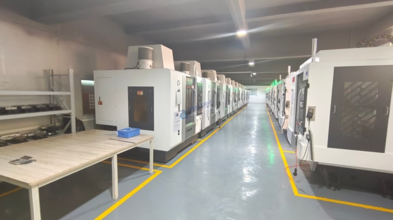
In the dynamic world of precision parts manufacturing, the quest for efficiency, versatility, and accuracy drives the adoption of advanced technologies. Among the cornerstone pieces of equipment in modern fabrication shops, the CNC router machine stands out for its unique capabilities in machining softer materials and producing large-scale components with intricate detail. Understanding how a CNC router machine works is fundamental for clients seeking the optimal manufacturing solution for their projects, whether they involve intricate signage, aerospace-grade composites, or custom architectural elements. This article delves into the operational principles, components, and process flow that define this versatile machine’s function.
H2: The Core Principle: Translating Digital Design into Physical Reality
At its heart, the fundamental operation of a CNC router machine is a symphony of coordinated motion guided by computer numerical control. It automates the process of cutting, carving, drilling, and milling by following a precise set of coded instructions—the G-code—generated from a 3D computer-aided design (CAD) model. Unlike manual routing, every movement of the cutting tool is pre-programmed, eliminating human error and ensuring exceptional repeatability across multiple parts. The machine’s core mission is to remove material from a workpiece (typically wood, plastics, composites, foam, and non-ferrous metals like aluminum) with high speed and positional accuracy, transforming a raw sheet or block into a finished component.
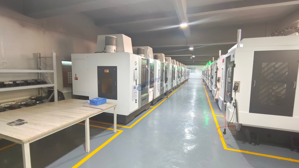
H2: Deconstructing the Machine: Key Components and Their Roles
To grasp how a CNC router machine works, one must first understand its major subsystems. Each plays a critical role in the machine’s precision and capability.
H3: 1. The Controller: The “Brain” of the Operation
This is the computer and software interface. It interprets the G-code program and converts it into electrical signals that command the motors. Modern controllers offer user-friendly interfaces for loading files, setting tool paths, and monitoring the job in real-time.
H3: 2. The Drive System: The “Muscles” and “Nerves”
Stepper or Servo Motors: These are attached to each axis of movement (typically X, Y, and Z). They receive signals from the controller to rotate by a precise amount.
Drives & Amplifiers: They boost the control signals to provide sufficient power to the motors.
Ball Screws or Rack-and-Pinion Assemblies: These mechanisms convert the rotational motion of the motors into the precise linear motion of the machine’s gantry or spindle.
H3: 3. The Mechanical Framework: The “Skeleton”
Base/Bed: A rigid, stable platform (often vacuum or T-slot table) that secures the workpiece.
Gantry: The bridge-like structure that moves along the Y-axis, carrying the Z-axis assembly. Its rigidity is crucial for maintaining accuracy during high-speed cuts.
Linear Guides/Rails: Precision-ground rails and bearing blocks that ensure smooth, friction-free, and accurate movement along all axes.
H3: 4. The Spindle: The “Tool Holder”
This is the high-speed motor that holds and rotates the cutting tool. Router spindles are designed for high RPM (revolutions per minute) operations, which are ideal for the materials they commonly process. Power can range from a few horsepower for hobbyist machines to over 20 HP for industrial models.
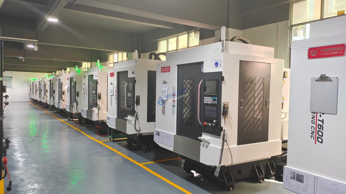
H3: 5. The Cutting Tool: The “Scalpel”
Various end mills, drills, and router bits made from carbide or high-speed steel are used. The tool’s geometry (flute count, diameter, coating) is selected based on the material and the desired cut quality.
H3: 6. The Vacuum System (Optional but Common): The “Grip”
A powerful vacuum pump is often connected to the bed to create suction through a perforated table or dedicated vacuum pods, firmly holding sheet materials flat without mechanical clamping that might interfere with the tool path.
H2: The Step-by-Step Workflow: From File to Finished Part
The operational cycle of a CNC router machine follows a logical, automated sequence:
Design & Programming (CAD/CAM): The process begins with a 3D CAD model of the part. Using CAM (Computer-Aided Manufacturing) software, a machinist or programmer defines the tool paths—selecting the appropriate tools, calculating feed rates, spindle speeds, and depth of cuts. The CAM software then “post-processes” this information into the machine-specific G-code.
Setup & Workholding: The raw material is securely fastened to the machine bed using clamps, screws, or, most commonly, the vacuum system. The correct cutting tool is loaded into the spindle, and its length and diameter are measured by a touch probe or manually set in the controller—a process called “tool setting.”
Zeroing & Reference: The machine’s coordinate system is synchronized with the workpiece. The operator sets the X, Y, and Z “zero points,” ensuring the machine knows exactly where the material is located in its workspace. This is a critical step for accuracy.
Execution & Machining: The operator initiates the program. The controller reads the G-code line by line, sending commands to the drive system.
The spindle spins up to the programmed RPM.
The drive motors move the gantry (X and Y) and spindle (Z) to position the tool at the starting point.
The tool plunges into the material and begins moving along the programmed path, removing material with each pass. The simultaneous interpolation of multiple axes allows it to create complex 2D profiles and 3D contours.
Completion & Unloading: Once the program finishes, the spindle retracts and returns to its home position. The vacuum is released, and the finished part(s) are removed from the bed. Any necessary secondary operations (like edge finishing or cleaning) are then performed.
H3: Key Distinctions: CNC Router vs. CNC Mill
While both are subtractive manufacturing tools, understanding their differences clarifies their optimal applications. A CNC router machine is engineered for speed and sheet-based processing of softer materials, featuring a lighter gantry structure, higher spindle speeds, and a large bed area. In contrast, a precision 5-axis CNC machining center, such as those utilized by advanced manufacturers like GreatLight Metal, is built for extreme rigidity and precision in machining hard metals (titanium, stainless steel) from solid blocks. It offers slower spindle speeds with much higher torque, a fully enclosed workspace for coolant management, and the ability to manipulate the part in multiple axes for truly complex, five-sided geometries.
Conclusion: The Strategic Role of the CNC Router in Modern Fabrication
Grasping how a CNC router machine works reveals it as more than just a cutting tool; it is a productivity multiplier that enables rapid prototyping, efficient batch production, and the creation of complex designs impossible to achieve manually. Its strength lies in handling large-format materials and softer substrates with remarkable speed and cleanliness. For projects requiring the ultimate in precision, material versatility, and the ability to tackle true 3D contours in engineering-grade metals, partnering with a manufacturer equipped with advanced multi-axis CNC machining centers becomes essential. Companies like GreatLight Metal leverage their deep engineering expertise and full-spectrum capabilities—from high-speed routing for prototypes to precision 5-axis CNC machining for flight-critical components—to guide clients in selecting the most efficient and cost-effective process for their specific material and tolerance requirements, ensuring every project benefits from the optimal manufacturing technology.
Frequently Asked Questions (FAQ)
Q1: What materials can a CNC router not machine effectively?
A: CNC routers are generally not suitable for machining hardened steels, titanium, or other super-alloys. These materials require the slower speeds, higher torque, rigid structure, and coolant systems of a dedicated CNC machining center to be cut efficiently and without damaging the router’s spindle or tools.
Q2: How does the precision of a CNC router compare to a CNC mill?
A: While modern industrial CNC routers offer excellent precision (often within ±0.001″ or 0.025mm for high-end models), they are typically optimized for speed over ultra-tight tolerances. A CNC mill, especially a 5-axis model, is designed for sustained machining at tolerances an order of magnitude tighter (e.g., ±0.0002″ or 0.005mm) on harder materials, thanks to its superior structural rigidity and thermal stability.
Q3: Can a CNC router perform 3D carving?
A: Absolutely. This is one of its key capabilities. By simultaneously controlling the X, Y, and Z axes, the router can move the tool vertically while tracing a path horizontally, allowing it to machine complex three-dimensional reliefs, molds, and sculpted surfaces.
Q4: What is the role of vacuum hold-down, and are there alternatives?
A: The vacuum table provides a fast, uniform, and unobstructed clamping force across the entire sheet material, which is ideal for cutting fully through a sheet (through-cuts) without hitting clamps. Alternatives include mechanical toggle clamps (for thicker materials) or fixture plates with threaded inserts for bolting down blocks of material.
Q5: Why would I choose a manufacturer with both CNC routers and multi-axis mills, like GreatLight Metal?
A: A manufacturer with a comprehensive equipment portfolio provides unbiased process engineering. They can recommend the most appropriate and cost-effective technology for your project stage—using a router for rapid, low-cost prototyping in acrylic or MDF, and then transitioning to a 5-axis CNC mill for final production in aluminum or stainless steel. This integrated approach, backed by deep technical support, ensures optimal outcomes from concept to final part. For further insights into advanced manufacturing partnerships, follow industry leaders on professional networks such as LinkedIn.



















