Taking the processing of the inner hole of the traction seat of the subway frame as an example, this paper presents a solution for processing thin-walled overhanging parts using the spiral layered milling method by analyzing the difficulties techniques, setups, tools and appropriate processing parameters. are selected to solve the problem of the treatment process. It solves vibration and power problems and meets process requirements.
1 Preface
The structure of the Type A metro is more complex than that of other metro models. The traction seat (see Figure 1) of this type of vehicle is a thin-walled overhanging part. Local processing elements have low structural rigidity and high precision requirements. The difficult thing is to process the inner hole of the traction seat on site. There is no corresponding processing experience and suitable production conditions. This article takes Shanghai Railway Line 18 as an example to analyze the technical difficulties of processing the inner hole of the traction seat, determine a reasonable process plan, and use the spiral layered milling method to process the parts in thin-walled overhang, thereby effectively ensuring product processing quality and efficiency.
Figure 1 Traction seat
2 Analysis of technological transformation difficulties
The technical difficulties of processing the inner hole of the traction seat of the type A subway frame are as follows.
1) The traction seat is a thin-walled overhanging part, which has poor rigidity and strong vibration during processing. There is a vibration phenomenon when processing the inner 42mm hole, resulting in poor surface processing quality. The success rate is only about 60%, which cannot meet the processing requirements.
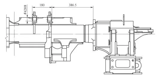
2) The 42H8 hole in the pull seat has high precision, and 4 tools are used during processing, which takes a long time. Due to the small space in the hole machining area, the existing tool does not have enough space for cutting. The cutting space L1=386.5mm, the width of the fixing head L2=205mm, the distance between the two ribs L3=180mm, the minimum length of the handle of the existing tool L4=40mm, L2+L3+ L4=425mm>L1 (cutting space).
3) There is no corresponding processing experience for new tools. If new cutting tools are purchased to solve the feeding gap problem and there is no relevant processing experience on site, it will be difficult to determine the feeding method and cutting parameters optimal to guarantee the effectiveness of the treatment and the quality of the product.
3 solutions
3.1 Difficulties
1) Solutions
Since the traction seat is a thin ribbed plate, adding an adjustable support rod between the two ribs (see Figure 2) can improve the rigidity of the traction seat during processing, reduce the vibration phenomenon when of the processing of the inner hole of φ42mm and ensure that the hole The surface treatment quality is excellent (see Figure 3) and the roughness of the inner surface of the hole 100% meets the requirements of the drawing.

Figure 2 Support rod

Figure 3 Surface treatment quality of holes
3.2 Difficulties
2) Solutions
(1) Solve the problem of knife feeding Cooperate with craftsmen to analyze the design drawings, contact the tool manufacturer, and produce a special extension tool for processing the inner hole of 42H8. The tool handle and tool shank are integrated, and positioning pins are added to the tool shank (see figure 4) and tool head (see figure 5), easy to position and tighten, determine the knife. The diameter of the rod is D=32 mm and the cutting head is removable. The length of tool handle and cutting rod is L4=130mm, the length of cutting head is L5=95mm, L2+L4=335mm[1]。

Figure 4 Tool holder

Figure 5 Locating pin
(2) Reduce the number of knives. The length of both cutter heads is designed to be L5 = 95mm. The cutting heads are removable and feature a positioning lock pin to improve fixation. The processing of the inner hole of φ42H8 can be completed using 2 tools (see Figure 6), one of which is a square shoulder cutter with a diameter of 32 mm and the other is a boring cutter with precision with a diameter of 42 mm. Compared to before the process plan improvement, 2 fewer tools will be used and only 2 manual tool changes will be required.

Figure 6 Machining tools
3.3 Difficulties
3) Solutions
(1) Select the optimal feeding method. Determine the diameter of the extended tool shank as D = 32 mm and use the spiral layered milling processing method (see Figure 7).[2]. Firstly, use a square shoulder milling cutter with a diameter of 32mm, and adopt a better processing method of spiral layered milling feed. After the spiral milling is completed, there is still a fine boring allowance of 0.4mm, then use a second fine boring cutter with it. a diameter of 42 mm. Linear interpolation feed for precision boring.[3]。

Figure 7 Spiral layer milling
(2) Select the optimal processing parameters. After repeated testing, the 32mm diameter square shoulder milling cutter has the best processing effect when using feed speed vf=200mm/min and rotation speed n=500rpm ; the cutter uses the feed rate. The processing results are better when the processing parameters of speed vf=15 mm/min and rotation speed n=600 rpm are taken into account. The surface roughness and hole processing size 100% meet the design requirements. is shown in Figure 8.

Figure 8 Treatment effect
4 achievements
Through hard work, we successfully completed the research on the spiral layered milling method based on the inner hole of the overhanging thin-walled workpiece and obtained the following results.
1) Improvement in the product qualification rate. The surface roughness qualification rate of the inner hole of Zhong42H8 has increased from 60% to 100%, which fully meets the requirements of processing technology.
2) Improved treatment efficiency. After the process improvement, the number of processing tools was reduced from 4 to 2, and the processing time of 2 42H8 inner holes was shortened by 18 minutes per rack.
3) Reduced costs. After the process improvement, the cost of the blade for processing the 42H8 inner hole was saved by 13.64 yuan/frame.
4) Technological promotion. The spiral layered milling method has been promoted and applied to other vehicle models with similar 42H8 hole structure in the traction seat of Type A subway.
5Conclusion
This article takes the subway frame traction seat as an example to analyze and solve the process difficulties and quality control difficulties in processing the inner hole of overhanging thin-walled parts. Using spiral layered milling technology, it ensures that the frame meets technical requirements. of the drawing after processing and improves processing efficiency, providing manufacturing experience for subsequent processing of similar products.
Daguang focuses on providing solutions such as precision CNC machining services (3-axis, 4-axis, 5-axis machining), CNC milling, 3D printing and rapid prototyping services.


