
7 Micro CNC Mastery Secrets for Unmatched Precision and Lower Costs
Seven process decisions that separate a shop hitting ±0.005 mm on one sample from one that holds it across a production run. Written for design and manufacturing engineers quoting micro features below 100 µm. After reading, you can judge which of the seven your current supplier actually controls.
What micro CNC mastery actually measures
Nominal capability is a brochure number. Repeatability is a process budget you can audit.
Machine architecture: 5-axis is not a 3-axis with a trunnion bolted on
A common mistake is treating a 5-axis machine as a 3-axis center with a rotary table added later. That arrangement stacks kinematic error instead of cancelling it. Every rotary axis carries its own backlash, angular positioning error and thermal growth, and those errors multiply through the tool tip. On a part with a 20 µm positional callout, the stack can consume the entire tolerance before the first chip is cut.
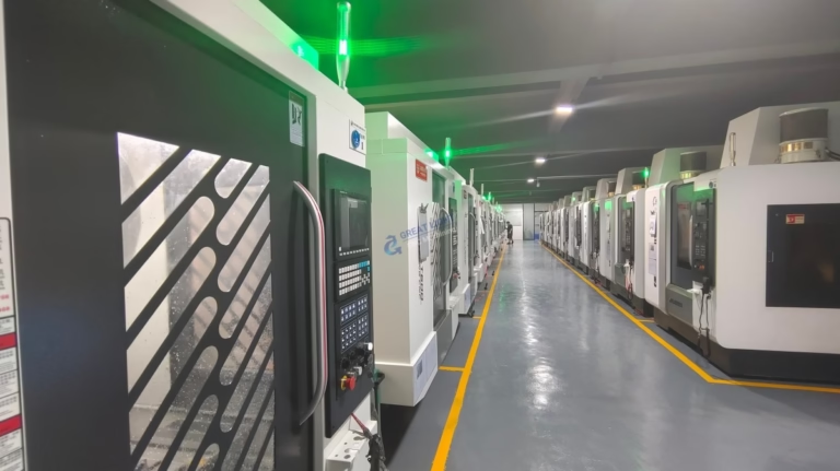
Machines built for simultaneous motion from the ground up behave differently. Structure, drives and cooling loops are sized together, so the rotary axes sit inside one thermal and kinematic model. GreatLight runs 16 simultaneous 5-axis machining centers alongside 12 four-axis mills and 27 three-axis machines, which means a job can be routed to the architecture it fits instead of being forced onto whichever spindle is free.
Decide by feature count and access, not by machine prestige. A micro part with features on three faces and a true position callout under 15 µm belongs on a simultaneous 5-axis machine in one setup. A flat plate with drilled holes does not. Paying for 5-axis time on a part that a 3-axis machine holds cold is one of the quietest cost leaks in micro work.
Micro tooling: the part CAM software forgets to model
CAM simulation treats a 0.5 mm end mill as a rigid cone. In the cut, that tool deflects, rubs and wears faster than the software predicts. Runout at the holder becomes the dominant error source. A 0.5 mm cutter with 5 µm of runout cuts a slot 10 µm wider than nominal, and no toolpath compensation will recover the difference on a finishing pass.
So the real control is upstream. Measure runout at the tool tip, not at the holder taper. Use shrink-fit or high-precision collets rated for the spindle speed you intend. Then adjust stepover and depth of cut to keep radial engagement low enough that deflection stays inside the tolerance budget. Feed and speed tables from a general catalogue rarely survive this step.
Tool life is also a metrology problem. A micro cutter that has run 40 minutes in titanium no longer cuts the same geometry it did at minute five. If your process plan does not define a tool change interval tied to feature criticality, the last parts in a batch will drift outside tolerance while the first parts pass.
Not every micro feature needs a micro tool. A 0.3 mm internal radius is cheaper to produce by EDM or by a smaller number of dedicated finishing passes than by a long, slow milling routine. Know when to stop milling.
Thermal stability is a process variable, not an environmental given
A temperature-controlled room is the starting point, not the answer. Spindle growth, ballscrew heating and coolant temperature all move the tool relative to the part during a cut. On a 50 mm long aluminium part, a 1 °C shift across the workpiece can move a bore by roughly 1 µm. On titanium, the same shift moves it less, but the cutting heat is higher.
The practical response is to let the machine reach thermal equilibrium before the first finishing pass, and to keep the roughing and finishing operations in the same thermal cycle where the geometry allows. Separating them overnight reintroduces the drift you just eliminated.
On long runs, monitor rather than assume. A part that measures in tolerance at 08:00 and out of tolerance at 14:00 is telling you the process, not the operator, has a thermal problem.
Which micro feature fits which process route
Use this to sanity-check a routing decision before you release a drawing.
| Feature | Typical route | Watch for |
|---|---|---|
| Internal radius under 0.3 mm | EDM or dedicated finishing pass | Tool deflection, electrode wear |
| True position under 15 µm, 3+ faces | Simultaneous 5-axis, one setup | Rotary axis backlash, thermal drift |
| Ra 0.2–0.8 μm sealing face | Fine finishing at low radial engagement | Tool runout, chatter marks |
| Micro slot under 1 mm wide | Micro end mill, shrink-fit holder | Chip evacuation, recast layer |
| Thin wall under 0.5 mm | Light radial passes, support fixturing | Deflection, workholding distortion |
Metrology that mirrors the machining, not just the final inspection
Final inspection catches a bad part. It does not tell you why the part went bad. In micro work, the measurement plan should follow the same sequence as the machining plan: raw material check, in-process monitoring on the critical features, then final inspection before shipment.
Choose the instrument to match the tolerance. A caliper is not a metrology tool at ±0.005 mm. CMM probing, optical measurement and surface profilometry each answer a different question, and a report that only shows a pass or fail verdict is not useful when a feature is marginal.
The number to protect is repeatability, not best-case accuracy. GreatLight inspects 100% of parts before shipment and provides reports on request. If a supplier cannot tell you which instrument measured which callout, the tolerance claim is not yet verified.
Surface integrity is a design intent, not a postscript
Two parts can pass the same dimensional check and behave completely differently in service. Surface integrity covers roughness, residual stress, microcracks and the recast layer left by thermal cutting. A sealing face at Ra 0.8–1.6 μm may be fine for a static joint and wrong for a dynamic one.
Specify the finish by function. As-machined surfaces at Ra 1.6–3.2 μm suit most structural interfaces. Fine finishing down to Ra 0.2–0.8 μm belongs where friction, sealing or fatigue life drives the design. Polishing or bead blasting changes the surface again, so sequence the finishing operations after the critical dimensions are confirmed.
On titanium and Inconel, control the cutting temperature. High edge temperature leaves a harder, more brittle layer under the surface, and that layer is where cracks start. Lighter radial engagement and generous coolant flow cost cycle time and buy fatigue life.
Process documentation: the part of the quote you never see
A supplier's certification list tells you what management systems exist, not what happened to your part. What matters is the process record: which machine, which tool, which fixture, which inspection data. Without it, a good first article cannot be repeated next quarter.
For regulated work, the paperwork carries the same weight as the geometry. GreatLight holds ISO 9001:2015, IATF 16949:2016, ISO 13485:2016 and ISO 27001:2022, which covers quality, automotive, medical device and information security scope. Ask for the certificate scope, not just the logo.
Material traceability belongs here too. If a run uses 17-4PH or Ti-6Al-4V, the heat lot and mill certificate should be attached to the same record as the inspection report. That single link is what makes a deviation investigation possible later.
Vertical integration: fewer handoffs, fewer ways to lose 10 µm
Every time a part leaves one building and enters another, it gets re-fixtured, re-datumed and re-inspected. Each handoff adds a small positional error and a large scheduling delay. Micro work punishes both.
Doing machining, finishing and inspection under one roof removes most of that. A part can be finished, measured and, if marginal, corrected before it is packed. The cost saving is not in the hourly rate. It comes from doing the job once, in one setup, with no re-clamping drift and no week lost to shipping between vendors.
GreatLight operates 3 wholly-owned plants across 7,600 m² with 150 technicians and 127 high-precision CNC machines, including 16 mill-turn centers. Maximum processing size reaches 4,000 mm, and the same floor handles anodizing, plating, bead blasting and laser marking. No minimum order quantity applies, from one prototype to 10,000+ part runs.
Vertical integration has limits worth naming. A shop that does everything rarely does every step at world-class level. What you gain is control of the interfaces, which in micro work is usually the larger win.
Questions engineers ask before releasing a micro part
What tolerance can we actually expect on a micro feature?
GreatLight works to ±0.005 mm (±0.0002 in) on qualifying features, with surface finishes from Ra 1.6–3.2 μm as-machined down to Ra 0.2–0.8 μm.
The achievable number depends on feature geometry, material and how many setups the part needs. Send the drawing and we return a DFM analysis with the tolerance we can hold on each callout.
When does 5-axis machining stop being worth the cost?
When the part can be reached from three directions or fewer and the positional callouts allow a single datum to survive two setups.
If the part needs features on four or more faces, or true position under about 15 µm, one simultaneous 5-axis setup usually beats multiple 3-axis fixtures on both accuracy and total cost.
How do you handle heat-sensitive micro parts?
Roughing and finishing stay in the same thermal cycle where geometry allows, and the machine reaches equilibrium before critical passes.
We monitor in-process on the features that drive function rather than assuming a stable room equals a stable cut.
Do you machine titanium and Inconel at micro scale?
Yes. TC4 (Ti-6Al-4V), TA1, TA2, Inconel and magnesium AZ31B or AZ91D are in our standard material range, along with 17-4PH and 316L stainless.
These materials need lower radial engagement and tighter tool change intervals. We define those in the process plan rather than leaving them to the operator.
What lead time and quantity should we plan for?
Quotation and free DFM analysis come back within 12 hours, and production can start within 24 hours. Parts typically ship in 3–5 days.
There is no minimum order quantity. One prototype and a 10,000+ part run go through the same inspection sequence.
How is our design protected?
Uploads are secure and confidential, and we operate under ISO 27001:2022 information security scope.
A non-disclosure agreement is available on request before you send any files.
Send the micro feature. Get the process route back.
Upload your drawing and we return a quotation with free DFM analysis within 12 hours, covering tolerance, finish and routing.
12-hour quoteFree DFM100% inspectionNDA on request









