
Why Do My Diamond Keep Fluctuating on CNC Machine?
Diamond fluctuating on CNC machine usually comes from five places: tool runout, spindle thermal growth, loose workholding, material inclusions, or chatter exciting a structural resonance. This guide gives you a symptom-cause-fix path so you can isolate the source in one shift instead of chasing it for weeks.
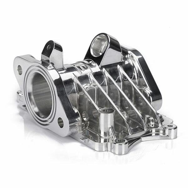
Symptom, likely cause, and first action
Start at the top. Each row is a symptom you can see or hear on the machine.
| Symptom | Likely cause | First action |
|---|---|---|
| Dimensional drift over a long cycle | Spindle or ballscrew thermal growth | Log part size every 20 min, watch for a steady trend |
| Ra value wanders between passes | Tool edge chipping or built-up material | Inspect the edge at ×200, re-lap or replace |
| Visible waviness at a fixed pitch | Workholding or spindle runout | Indicate the fixture and tool holder on the taper |
| Audible tone that rises with speed | Chatter exciting a structural mode | Tap-test the setup, change spindle speed by 10% |
| Step marks after an index move | Servo mismatch or backlash | Check backlash with a dial indicator on each axis |
| Random spikes in one direction | Material inclusion or hard spot | Cut a test ring, map the spike against the bar |
| Taper across the face | Leveling or geometry error | Re-level the bed, re-check squareness |
Fix the setup, not the diamond
In most cases the diamond is innocent. Warm up first, indicate the tip, and check the fixture before you touch the tool. The error is almost always thermal, mechanical, or fixturing.
What actually makes a diamond tool wander
A diamond tool does not flex. It is far harder than the workpiece, and it will not absorb a bad setup the way carbide does. When readings drift, the diamond is reporting a problem in the machine, the holder, the fixture, or the material. Treat it as a sensor, not the fault.
Single-point diamond turning holds tighter numbers than most milling work. Our floor runs to ±0.005 mm (±0.0002 in) and Ra 0.2–0.8 μm on non-ferrous parts, and at that level a 2 μm shift shows up immediately in the Ra trace. A 5 μm shift will scrap an optic. So the threshold for what counts as a real problem is low, and small errors matter.
The error chain has five links: spindle, tool holder, tool edge, workpiece, and structure. Each link adds its own error. Fix them in order. Measuring the last link first wastes hours.
- 1Runout compoundsSpindle error plus holder error plus edge offset adds up, not averages out.
- 2Heat is slowSpindle growth takes 30–60 min to settle, so short test cuts can look fine.
- 3Chatter is speed-sensitiveA 10% spindle speed change can move you off the resonance.
- 4Material is not uniformCastings and extruded bar carry hard spots and residual stress.
Spindle thermal growth and how to prove it
The spindle warms up as it runs. Bearings, motor windings, and the coolant loop all add heat. The housing and the shaft expand at different rates, so the tool center point moves. On an air-bearing spindle the shift is often 3–8 μm over the first hour. Oil hydrostatic spindles behave differently again.
You can prove it with a simple test. Face a test disc, let the machine idle 30 min, then face it again at the same coordinates. Measure both surfaces. If the second cut is deeper by a few microns, thermal growth is the cause. No amount of tool inspection will fix that.
The fix is a warm-up routine before every production run, not just on Monday morning. Run the spindle at the production speed for 30–45 min, or program a warm-up cycle that matches the real cutting load. Keep the coolant temperature within ±1 °C. If the shop door opens onto a cold yard, the draft alone can shift a large part.
- 1Warm-up 30–45 minMatch the warm-up speed to the production speed.
- 2Coolant ±1 °CA chiller that hunts by 3 °C will show in the finish.
- 3Log the driftRecord part size every 20 min for the first two hours.
Tool runout, edge condition, and holder mistakes
A diamond edge is fragile in a way carbide is not. A small chip on the flank changes the effective radius, and the depth of cut changes with it. Inspect the edge at ×200 or better before you blame the machine. Look for chipping, a worn flank, or built-up aluminum smeared on the rake face.
Runout is the second suspect. Indicate the tool tip, not the holder body. On a diamond turning setup, aim for total runout under 2 μm. If you see 5 μm, check the holder taper for dents, check the collet for a trapped chip, and check that the tool is seated flat. A single chip under the seat can tilt the tool and cause a taper across the face.
Tool height also matters. On a radius tool, if the tip sits above or below center by more than about 5 μm, the effective rake changes and the surface finish degrades on one side of the part. Set height with a test cut and a microscope, not by eye.
- 1Inspect at ×200Look for chipping and built-up material before anything else.
- 2Indicate the tipHolder body runout tells you nothing about edge position.
- 3Clean the seatA trapped chip tilts the tool and creates a taper.
- 4Set height by test cutAim for ±5 μm on the tool center height.
Fixturing, clamping force, and part distortion
Soft materials move when you clamp them. Aluminum and copper will distort under a chuck or a vise, and the distortion releases as you cut. The part springs back, and the diamond cuts a different depth than the one you programmed. That shows up as a face that is round in the chuck and out of flat once released.
Check clamping pressure. Use the lowest pressure that holds the part safely. For thin discs, support the back with a vacuum chuck or wax, and cut light passes. A 0.05 mm depth of cut with a 0.4 mm nose radius is often enough. Heavy roughing passes on a thin part will always move it.
Also check that the fixture is rigid in the thrust direction. If the part can slide a few microns under cutting load, the tool will follow it. Dial-indicate the part, push it by hand, and watch for movement. Any visible needle movement means the fixture needs work.
Six steps to isolate diamond fluctuation
Work in this order. Each step rules out one link in the error chain.
- 1Warm up the machineRun the spindle at production speed for 30–45 min. Keep coolant within ±1 °C. This removes thermal growth as a variable before you measure anything.
- 2Inspect the diamond edgeClean the tool and inspect at ×200 or higher. Look for chipping, a worn flank, or built-up material. Replace or re-lap if you see damage. A chipped edge will never hold size.
- 3Indicate the tool tipMeasure runout at the tip, not the holder. Target under 2 μm. Clean the taper and the seat, then re-check. If runout stays high, swap the holder.
- 4Check workholding rigidityDial-indicate the part and push it by hand in the cutting direction. Any needle movement over 2 μm needs a fixture fix. Reduce clamping pressure on soft materials.
- 5Cut a test ring and measureFace a test disc at the production speed and feed. Measure flatness, size, and Ra. Record the numbers so you can compare after each change.
- 6Tap-test and adjust spindle speedIf you hear chatter, tap-test the setup to find the natural frequency. Change spindle speed by 10% and re-cut. Move the speed until the tone disappears.
Frequently asked questions
Why does my part measure fine on the machine but out of tolerance after it cools?
The part is measuring the machine's thermal state, not its own. When the spindle and the part both cool, the part shrinks and the fixture releases. Measure at a stable 20 °C.
Log the part size every 20 min through a full cycle. If the number drifts in one direction, thermal growth is the cause. Add a warm-up routine and re-check.
Can a worn diamond tool cause the size to fluctuate?
Yes. Flank wear changes the effective nose radius, so the depth of cut changes with it. A small chip does the same thing, but in a step.
Inspect the edge at ×200 before every long run. If you see a chip wider than about 5 μm, replace or re-lap the tool. Do not try to cut through it.
How much tool runout is acceptable for diamond turning?
Aim for total runout under 2 μm at the tool tip. Above 5 μm you will see the error in the surface finish and in the size across the face.
Indicate the tip, not the holder body. Clean the taper and the seat, and check for a trapped chip before you blame the spindle.
Why does the finish change when I move the machine to a different bay?
Floor vibration and temperature both change. A machine near a stamping press or a forklift route sees more low-frequency energy, and that shows up as waviness.
Check the foundation, the leveling pads, and the ambient temperature at the new location. Re-level the bed and re-check squareness before you cut.
Does coolant type affect diamond tool fluctuation?
It can. Some fluids leave a residue that builds up on the rake face and changes the cutting edge. Others do not cool evenly, so the part grows and shrinks during the cycle.
Use a clean, filtered fluid and keep the temperature within ±1 °C. Change the filter on schedule. A dirty fluid carries chips back into the cut.
When should I stop troubleshooting and send the job out?
If you have checked thermal growth, runout, the edge, and the fixture, and the fluctuation is still there, the problem is likely in the machine geometry or the control loop.
That is the point to bring in a service technician or move the job to a shop that runs the same process every day. Guessing past that point costs more than the parts.
Send us the drawing and the Ra target
We run diamond turning on non-ferrous parts to ±0.005 mm and Ra 0.2–0.8 μm. Quotation and free DFM analysis within 12 hours.
12-hour quote100% inspectionNo minimum orderNDA on request
More from GreatLight
We publish setup notes, tooling trials and inspection data from the factory floor.











