Deep bore processing has always been a difficult problem in machine and mold processing. Previously, a colleague encountered the problem of processing a 48 × 215 mm deep hole on a pipe mold. He now shares the pitfalls he stepped on, hoping to provide help and referrals.
Part drawing analysis and process planning
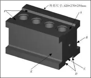
1.Analysis of the part drawing
The parts of the pipe mold are shown in Figure 1. There are 4 holes with a diameter of 48 × 215 mm and a depth that need to be processed. The overall dimensions are 420 × 270 × 250 mm. There are 4 grooves on the upper, lower, left and right sides. There are steps on the hole surface and slopes on both sides as row matching surfaces.
Figure 1 Pipe Mold Parts
The process requirements of this part are that the hole taper cannot exceed 0.1mm, the surface roughness value is Ra3.2μm, the hole distance tolerance cannot exceed 0.03mm and the verticality is 0.03 mm. glass pipe and its wall thickness is only 0.8mm. Customers who need thickness greater than 0.8mm will not receive the goods. It can be said that the thinner the better, just to save costs.
At that time, I really wasn’t sure about such a difficult piece. Although the author’s unit was only responsible for processing deep boreholes, customers could cooperate with other aspects of processing. After many attempts, a simple and reasonable treatment plan was finally developed.
2. Process planning
(1) Simple processing sequence before boring parts
After the thin material is tempered, the milling machine first processes the grooves on both sides. As shown in Figure 1, B and E are first rough, then fine, and are processed to the desired number.
The steps on the front face of the treatment are roughened, leaving a margin of 0.5 mm on one side, as shown at A and F in Figure 1.
The steps on the bottom surface of the machine are roughened, leaving a margin of 0.5 mm on one side, as shown at C and D in Figure 1.
Then reinstall the clamping and calibration, center the four sides, drill and position the center step by step, drill bits with a diameter of 10mm, a diameter of 24mm and a diameter of 35mm are used . A drill bit with a diameter of 44 mm is used for drilling and roughing.
When finished, wet grind the surface and bottom as shown in Figure 2 and grind to a certain number to ensure that the parallelism is 0.03mm.


Figure 2 Parts Dimensions Diagram
As shown in Figure 1, a finishing allowance of 0.3 mm is reserved for side grinding of B and E.
(2) Clamping and part positioning data
The workpiece is directly clamped on the CNC workbench, and the four feet of the mold are respectively closely coded. The calibration table is accurate and the error is controlled within 0.03mm.
CNC machining of parts
1.Analysis of the part drawing
Homemade boring tool: First make a boring tool holder as shown in Figure 3. The material is 837H. It is first roughly turned, leaving a margin of 0.5 mm. After heat treatment, it is processed with a cylindrical grinder. coaxiality. The small knife holder with blade is purchased as a standard 10x10mm piece, making blade replacement easy and ensuring size.
The inclination angle of the small integrated tool holder is 20°. It is wire cut and has a slightly snug fit. The boring tool holder is drilled with M6mm hexagon socket screws, and the small tool holder is locked with the hexagon socket screws. The standard small tool holder is equipped with a carbide blade, with a main deviation angle of 30°, a flank surface clearance angle of 15°, and an angle R0.3 ~ R0.4mm at l end of the blade to minimize the contact surface to avoid vibration.
2. Determine the treatment plan
(1) Hole processing plan 1 uses rapid wire cutting. This method is the most direct and simple and does not require rough cutting. However, because the size is too deep (215mm), cooling and rinsing during processing is difficult to solve. and the wire is easy to break and the surface is rough. The degree value does not meet the requirements.
(2) Hole processing plan 2 uses slow wire processing. Due to the depth of the hole, the wire is easy to break. However, the processing fee for each hole is around 1,945 yuan. The total mold wire cutting cost is close. 7,700 yuan, which far exceeds the customer’s cost calculation.
(3) Hole processing plan 3 CNC profile milling, use extended tool handle to install round tool particles or diamond-shaped alloy tool particles, and perform deep layer processing. Due to the large contact area, the sound is very loud and harsh every time. At the time when the tool is entered and withdrawn, the roughness value of the processed surface and the dimensional accuracy are very poor, and there are undercut grooves from time to time. Roughness alone cannot be controlled and is far from standard.
(4) Hole processing plan 4 CNC boring processing, the model used is 850B, general machine tools can be used, the Z axis height of this model is 500mm, which can meet the processing requirements of boring tool holder 230 and hole workpiece depth 250mm and the total processing time for each hole is only 2 hours. The processing precision is high, and the surface roughness value and dimensional accuracy meet the drawing requirements.
By comparing the cost, machining accuracy and ease of processing, the hole processing plan of plan 4 was selected.
3. CNC boring processing process
(1) Clamp and align the workpiece on the machine tool, clamp the four corners, and level the parallel position and level of the workpiece. If they exceed 0.03 mm, the upper and lower sides of the workpiece must be ground, otherwise this will be the case. be difficult to ensure the verticality of the hole. The calibration tolerance is controlled within 0.02mm. Among the 4 surfaces, the surface of the second stage is used as the 0 surface of the Z axis to be processed, and there is as much space as possible for the tool to be lifted.
(2) Install the boring tool holder. Use a table card to measure the size of the boring blade higher than the large tool holder for the first rough machining. Reserve about 0.5mm on one side for rough machining to facilitate semi-finishing. The main deflection angle of the boring insert is 30°, the flank clearance angle is 15°, and the tool tip fillet is an angle of R0.3 to R0.4 mm, minimizing the contact surface and stresses to avoid undercuts due to vibrations. The surface of the workpiece facing the tip of the boring tool is surface 0.
(3) G76X_Y_Z_R_Q_P_F_ boring program command format;, G76 is precision boring command, X/Y/Z coordinate position of the hole, P is the break at the bottom of the hole, Q means the tool is paused and shifted after processing, to avoid scratches when lifting the tool. The wounds were treated on the side.
(4) Rough machining parameters: speed S is 120 rpm, feed F is 80 mm/min, cutting quantity is 1.0 mm, cutting oil is liquid cooling, oil fluidity should be good and cooling is in place.
(5) Semi-finishing parameters are set. After the rough machining is completed, the card number and inspection are carried out. The size of the deep inner hole can be measured with an inner hole gauge. There will usually be some taper. the speed S is 110rpm and the feed F is 70mm/min, the cutting quantity is 0.6mm, the cutting oil is a coolant, the fluidity of the oil should be good and cooling is in place to ensure roughness of finish. .
(6) Adjusting finishing parameters: Use a new blade to process each hole. The rotation speed S is 100 rpm and the feed F is 60 mm/min. Use a micrometer card to measure the position of the blade and lock the small tool holder. for treatment. Test the hole processing first, because there is a 15mm pitch on the top surface of the part, until the size reaches the drawing requirements.
Writing the program

Note: Only the values of F and S in the program content can be changed for rough machining, intermediate machining and finish machining.
This set of machining plans has been improved several times on site. It started with the contour machining plane, the tool had to be lifted and changed several times during the process. The machining time for each hole was approximately 4 hours. The processed value made the customer very satisfied. The headache made the second machine-saving mold polishing process take a day, and the roundness of the polished round hole was not up to standard.

Figure 3 Boring tool holder
Boring processing mainly involves adjusting two parameters: feed and speed. The feed rate is normally calculated as Vc=πDN/1000. After numerous on-site processing and continuous improvement, it was finally concluded that the finishing speed S is 100 rpm, the feed F is 60 mm/min. Although the result is simple and requires a lot of effort, it can be concluded that intermediate/semi-finishing machining and finishing machining can be completed in one go. of each hole is within 2 hours. Cylindrical The degree and roughness values all meet the standards, which reduces the customer’s secondary processing time, truly improves production efficiency, and has won the praise of customers.
Although this set of final bore treatment plans is simple, the process is really not easy. If a detail is missing, the treatment effect may be different. The biggest concern for deep hole reaming is the fear of vibration during processing and excessive force. If it is reversed, the part will be scrapped. Therefore, I hope it can bring you some references in terms of blade selection, precautions and other processing parameters.
Daguang focuses on providing solutions such as precision CNC machining services (3-axis, 4-axis, 5-axis machining), CNC milling, 3D printing and rapid prototyping services.


