
What Is CNC Machine Programming?
CNC machine programming is how a 3D model becomes a set of instructions a machine tool can follow. This page walks through the workflow, the code, and the decisions that affect tolerance and cost. It is written for design engineers and buyers who review quotes and need to know where the risk sits.
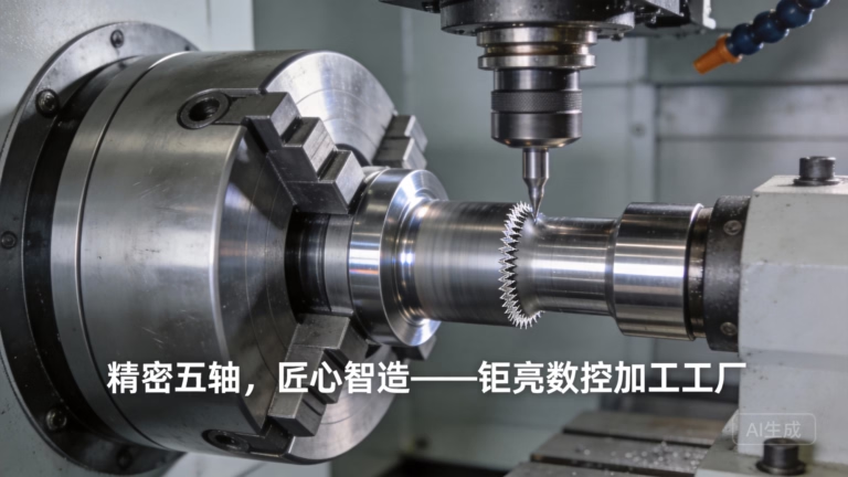
CNC machine programming turns geometry into motion
CNC machine programming is the step between a finished CAD model and a cut part. A programmer takes the model, decides which tools and fixtures will hold the part, and writes the instructions the machine controller executes. Every line describes a motion, a speed, a feed, or a change of tool.
The instructions are not generic. A three-axis mill, a mill-turn center, and a wire EDM all read different code and have different kinematic limits. The same part programmed for a three-axis machine may need two setups; programmed for a five-axis center it may need one. The geometry is fixed. The program decides how many times the part is touched.
This is why programming shows up in the quote. More setups mean more fixture work, more chances for stacked tolerance error, and more hours. A clean program removes setups, not just keystrokes.
- 1Setup count is a design decisionEach new orientation adds datum error and labor.
- 2The controller is the final authorityFeed and speed limits come from the machine, not the CAM default.
The five stages of a CNC program
A program does not appear in one step. It moves through five stages, and each one can send the job backward if the input is wrong. The first stage is the CAD model itself. Holes without a defined depth, threads without a class, or sharp internal corners that no end mill can reach will stall the process. A machinability review catches these before programming starts.
Stage two is toolpath planning. The programmer chooses stock size, workholding, and the order of operations: face, rough, semi-finish, finish, then drill and tap. Roughing removes volume fast with a large stepover. Finishing runs slower with a small stepover to hold the surface finish. On aluminum, roughing may run 3–5 mm depth of cut; on 17-4PH stainless that number drops to 0.5–1.5 mm.
Stage three is CAM output. The software generates toolpaths and posts them into machine-specific code. Stage four is verification. The programmer simulates the toolpath, checks for gouges and collisions, and confirms the part sits inside the stock. Stage five is proving out on the machine: run the first part, measure it, adjust offsets, and release the program for the run.
A proven program is an asset. Repeat orders that reuse it skip most of stages two through five, which is why a stable design held across orders tends to get cheaper over time.
- 1CAD modelComplete geometry with tolerances and thread specs.
- 2Toolpath planningStock, workholding, rough and finish strategy.
- 3Post-processingGeneric toolpaths converted to controller-specific code.
- 4Prove-outFirst article measured, offsets dialed, then released.
How axis count changes the program
Axis count is the single biggest lever in programming. On a three-axis machine the tool always points down. Any feature on the side of the part needs a second setup, and every re-clamp introduces a new datum that must agree with the first. For a bracket with four side holes, that is two setups and two chances to drift.
A four-axis machine adds a rotary table, usually Ø400 mm on our mills. The part rotates around one axis while the tool cuts, so features on four faces can be reached in one setup. A five-axis center adds two rotary axes that move at the same time. The tool can tilt to approach an angled face at the correct angle instead of leaving a scalloped surface from a ball nose cutter.
The trade-off is real. Five-axis programming takes longer to prepare, the machine is more expensive per hour, and the post-processor must be exact. For a simple plate with top-face features only, three-axis is faster and cheaper. For an impeller, a medical implant with compound curves, or a deep cavity with undercuts, five-axis removes setups that would otherwise dominate the cost.
- 13-axisBest for prismatic parts with features on one face.
- 24-axisCylindrical parts, slots, and holes around a single axis.
- 35-axisCompound angles, undercuts, and single-setup complex parts.
Why programming decides whether you hold ±0.005 mm
Tolerance is not only a machine spec. A machine that can position to ±0.005 mm will still miss if the program asks for a full-depth finish pass in one cut. Deflection pushes the tool away from the wall, and the part comes out undersized on a heavy pass or oversized after springback. The programmer controls this by leaving a light finishing allowance, often 0.2–0.5 mm, and taking it in a separate pass.
Thermal behavior matters too. A long roughing cycle heats the part and the spindle. If the finishing pass runs immediately, the part is still warm and will shrink when it cools. Programs for tight-tolerance parts often include a cool-down pause before the final cut.
Surface finish is programmed as well. Ra 1.6–3.2 μm is a normal as-machined finish. Ra 0.8–1.6 μm needs a finer stepover and a sharper tool. Ra 0.2–0.8 μm usually means a dedicated finishing pass with a small nose radius, sometimes followed by polishing. Asking for a mirror finish on a part that only needs Ra 1.6 μm adds cost with no functional gain.
Tool wear is the last variable. A program that assumes a fresh cutter for a 10,000-part run will drift as the tool wears. On long runs, programmers add wear offsets that the operator updates, or split the run into batches with a tool change between them.
- 1Finishing allowanceTypically 0.2–0.5 mm left for the last pass.
- 2Cool-down before finishPrevents shrinkage error on tight parts.
- 3Wear offsetsKeep long runs inside tolerance as tools dull.
What in the part raises programming effort
Deep pockets are the classic example. A pocket deeper than about three times the cutter diameter needs a long, thin tool that deflects. The programmer has to slow the feed, step down in small increments, and often use a smaller cutter first. A pocket at four times diameter can take several times longer than one at two times diameter.
Sharp internal corners force a small cutter. If the drawing calls for a 90° internal corner with zero radius, no round tool can produce it. The practical answer is to leave the largest radius the function allows. A 1 mm corner radius on a pocket floor is usually fine and lets the programmer use a much stiffer tool.
Thin walls vibrate. A 0.8 mm wall on an aluminum housing will chatter if the program takes a heavy pass, leaving a rough finish and possibly a bowed wall. The fix is a lighter, faster pass with more coolant and sometimes a support. It also means the programmer may need to leave material on the wall and finish it after the rest of the part is cut.
Tapped holes look simple until the thread depth, class, and material are considered. A blind M3 hole in 316 stainless at 2.5× diameter depth is a tap-break risk. The program needs peck tapping, a specific feed, and often a slightly larger pilot drill than the chart suggests.
- 1Pocket depth over 3× tool diameterLonger cycle, more deflection risk.
- 2Zero-radius internal cornersImpossible with round cutters; add a radius.
- 3Walls under 1 mmChatter and bowing; needs light passes.
G-code, M-code, and CAM output at a glance
What each element controls on the shop floor
| Element | What it controls | Typical example |
|---|---|---|
| G-code | Motion type and path | G01 linear feed, G02 arc |
| M-code | Machine functions | M08 coolant on, M06 tool change |
| Coordinates | Where the tool goes | X, Y, Z, plus A and B on 5-axis |
| Feed rate | How fast the tool advances | 800 mm/min in aluminum roughing |
| Spindle speed | Tool rotation in rpm | 8,000 rpm with a Ø10 mm end mill |
| Tool offset | Length and diameter compensation | G43 length, G41 cutter comp |
| Work offset | Part zero in machine space | G54 through G59 |
When to leave programming to the shop
If your part is prismatic and fits one or two setups, a simple CAM job is enough and you can review the setup sheet yourself. If it has compound angles, deep cavities, thin walls, or tight tolerances on more than one face, send the model to the shop and let the programmer choose the axis count and the toolpath. That decision drives tolerance and cost more than any drawing note.
Common questions about CNC machine programming
Do I need to send G-code with my CAD model?
No. Send the 3D model and a 2D drawing with tolerances, thread specs, and any critical dimensions. The shop generates the code for its own machines.
Pre-written G-code from another shop often does not match the controller, the tool library, or the fixture. It can be used as a reference, but it usually gets rewritten.
What file format is best for programming?
STEP is the safest choice because it carries solid geometry without translation errors. IGES works for surfaces but can leave gaps.
For parts with tight tolerances, send a native CAD file plus a PDF drawing. The drawing carries the tolerance callouts that the model alone does not.
How much does programming add to the part price?
On a first order, programming can be a noticeable share of the price, especially for five-axis work. On repeat orders that reuse the proven program, that share drops to near zero.
The bigger cost driver is usually setup count, not code length. A program that removes one setup often saves more than it costs to write.
Can you program for materials like titanium and Inconel?
Yes. Titanium and Inconel cut differently from aluminum. Speeds and feeds drop sharply, and the program needs more coolant and shorter passes to control heat.
We program for TA1, TA2, TC4 (Ti-6Al-4V), Inconel, and magnesium alloys alongside aluminum, stainless, and steel.
How do you handle confidentiality of the CAD files?
Uploads are treated as confidential. We can sign an NDA on request before files are shared.
Programs and models are stored internally and are not shared outside the job.
What tolerance can programming realistically support?
Our machines hold ±0.005 mm (±0.0002 in) on suitable parts. Whether a specific feature reaches that depends on geometry, material, and feature size, not on the code alone.
A thin wall or a deep pocket may be limited by deflection long before the machine reaches its positioning limit.
Send the model, get a programming-aware quote
We review the geometry, choose the axis count and setup strategy, and return a quotation with a free DFM analysis within 12 hours.
12-hour quoteDFM analysis includedNDA on request100% inspection
More from the shop floor
We publish setup notes, tooling trials and inspection data from the factory floor.











