
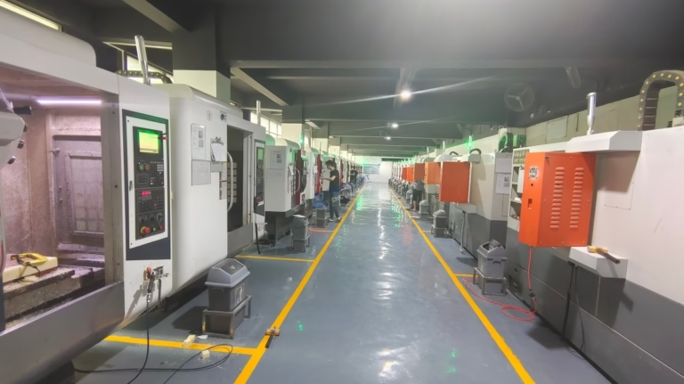
When embarking on a precision machining project, one of the most fundamental yet critical questions that arises is: what file format do CNC machines use? The answer is not a single file extension but a journey through a digital pipeline, transforming a designer’s vision into physical reality. For engineers, procurement specialists, and innovators seeking reliable manufacturing partners like GreatLight Metal, understanding this workflow is key to ensuring a seamless, accurate, and efficient production process.
At its core, CNC machining is a subtractive manufacturing process where a computer-controlled machine tool follows a set of coded instructions to carve a solid block of material into a finished part. The file format acts as the universal language between your design and the machine. However, this “conversation” happens in stages, involving different file types for different purposes.
The Digital Journey: From CAD to CAM to CNC
The path from a 3D model to a machined part typically involves three key stages, each with its preferred file formats:
1. Design & Conceptualization: The CAD Stage
This is where it all begins. Engineers and designers create the 3D model of the part using Computer-Aided Design (CAD) software. The native files from these programs (like .sldprt for SolidWorks, .prt for UG/NX, or .ipt for Inventor) contain the full “intelligence” of the design—features, dimensions, constraints, and assembly relationships.
Primary Formats at This Stage:
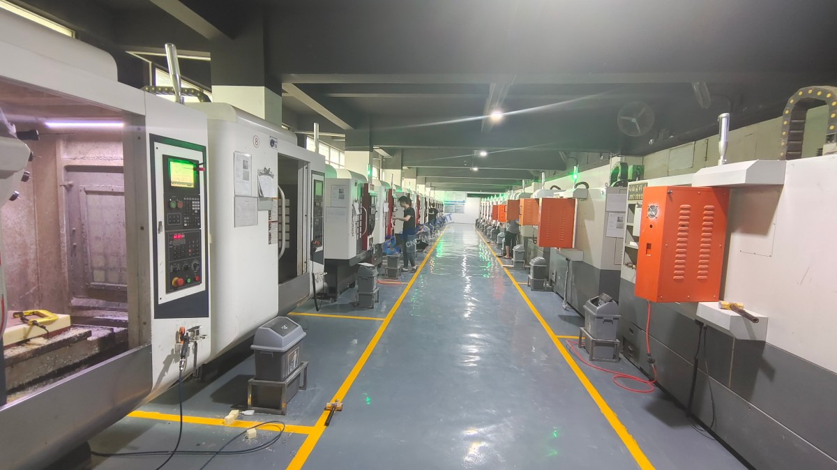
STEP (.stp, .step): The undisputed champion for design interchange. It is an ISO-standard neutral format that preserves solid geometry, assembly structure, and even color data. It is the most reliable and recommended format for sending designs to a manufacturer like GreatLight Metal.
IGES (.igs, .iges): An older, surface-based neutral format. While still widely supported, it can sometimes lead to translation errors with complex solid geometries and is generally considered less robust than STEP.
Parasolid (.x_t, .x_b): A robust, kernel-based format native to many CAD systems. It is excellent for precision but requires the receiving party to have compatible software.
A Note on STL (.stl): While ubiquitous in 3D printing, STL is a mesh format that approximates surfaces with tiny triangles. For CNC machining, it is less ideal for high-precision work because it loses all parametric data and intelligent features, making it difficult to validate critical dimensions directly. Its use should be limited to preliminary prototyping or when no other format is available.
2. Manufacturing Planning: The CAM Stage
Once the CAD model is received, manufacturing engineers import it into Computer-Aided Manufacturing (CAM) software. Here, they define the machining strategy: selecting tools, setting cutting paths, speeds, feeds, and generating the machine-specific code. The CAD file (STEP is ideal) serves as the accurate geometric reference.
3. Machine Execution: The G-code Stage
This is the answer to the core question. CNC machines themselves ultimately run on G-code. G-code (with extensions like .nc, .cnc, or .tap) is a standardized, but often machine- or controller-specific, programming language (e.g., ISO code, Heidenhain). It consists of a series of alphanumeric commands that tell the machine exactly where to move, how fast to spin the tool, and at what rate to feed.
Key Point: You, as the client, almost never need to provide G-code. A competent manufacturer like GreatLight Metal will generate this in-house after thorough process planning and verification. Providing your own G-code can even be risky, as it bypasses the manufacturer’s expert optimization and validation steps.
Why Your Choice of Initial Format Matters: Avoiding the “Precision Black Hole”
Selecting the right file format at the outset is the first defense against the common industry pain point known as the “Precision Black Hole”—the gap between promised and delivered accuracy.
Preserving Design Intent: Formats like STEP ensure that every datum plane, critical tolerance, and geometric feature in your original CAD model is accurately transferred. This eliminates interpretation errors that can occur with less robust formats.
Enabling Manufacturability Analysis: With a high-fidelity model, engineers can perform Design for Manufacturability (DFM) analysis, identifying potential issues like hard-to-machine features, insufficient wall thickness, or inappropriate tolerances before cutting metal.
Streamlining Communication: A standardized format like STEP acts as a universal language, ensuring clear, unambiguous communication between your design team and the manufacturing experts at GreatLight Metal.
Best Practices for Submitting Your Design Files
To ensure your project starts on the right foot, follow these guidelines:
Primary Submission: Always provide the 3D model in STEP format (.stp or .step). This is the gold standard.
Supporting Documentation: Include 2D drawings in PDF format. While the 3D model is primary, 2D drawings are invaluable for specifying critical dimensions, geometric tolerances (GD&T), surface finishes, threading notes, and other manufacturing callouts that are not easily embedded in a 3D file.
Archive Native CAD (Optional but Helpful): It can be useful to include the native CAD file (e.g., SolidWorks .sldprt) in a zip archive as a reference, but the STEP file should remain the master for manufacturing.
Clearly Define Requirements: In your RFQ, specify materials, quantities, key tolerances, and post-processing needs (anodizing, plating, etc.).
How GreatLight Metal Navigates the File Format Ecosystem
As a manufacturer with deep technical expertise, GreatLight Metal has built a robust digital workflow to manage this process seamlessly:
Advanced CAD/CAM Software Suite: They utilize industry-leading software to import and work with all major CAD formats, ensuring no data is lost in translation.
Engineer-Led DFM Process: Upon receiving your STEP file, their engineering team conducts a thorough analysis, not just to program the machine, but to optimize the manufacturing process for quality, speed, and cost. They will proactively engage with you if any potential issues are spotted.
In-House G-Code Generation & Simulation: All toolpaths are generated in-house and run through advanced simulation software to detect potential collisions, optimize machining time, and ensure the program is flawless before it ever touches one of their advanced 5-axis or multi-axis CNC machining centers.
Full-Digital Traceability: From your original submitted file to the final inspection report, the digital thread is maintained, ensuring accountability and quality control aligned with their ISO 9001:2015, IATF 16949, and ISO 13485 certified management systems.
Conclusion
So, what file format do CNC machines use? The machine tool itself speaks G-code. However, your journey as a client begins with providing a high-quality, precise STEP file alongside clear 2D drawings. This choice sets the foundation for a successful partnership. By entrusting your design to a manufacturer that combines technical hard power—like a comprehensive fleet of precision CNC equipment—with the systemic soft power of rigorous engineering analysis and international certifications, you bridge the “precision gap” with confidence. Choosing a partner like GreatLight Metal means selecting a team that expertly navigates the entire digital-to-physical workflow, transforming your optimal file format into a perfectly machined component.
Frequently Asked Questions (FAQ)
Q1: Can I just send an STL file for CNC machining like I do for 3D printing?
A: While possible, it is not recommended for precision parts. An STL file is a polygonal mesh approximation of your model. It lacks the precise mathematical definition of surfaces and edges found in a CAD-native or STEP file, making it unsuitable for defining tight tolerances. It can lead to interpretation errors and should only be used for rough prototypes or when no other option exists.
Q2: My supplier asked for G-code. Should I provide it?
A: Generally, no. Generating G-code requires deep manufacturing expertise, knowledge of specific machine tools, cutting tools, and fixturing. By providing G-code, you assume full responsibility for the machining strategy and potential errors. A full-service manufacturer like GreatLight Metal expects to generate optimized, machine-specific G-code as part of their value-added service and quality assurance process.
Q3: What’s the difference between STEP and IGES? Which is better?
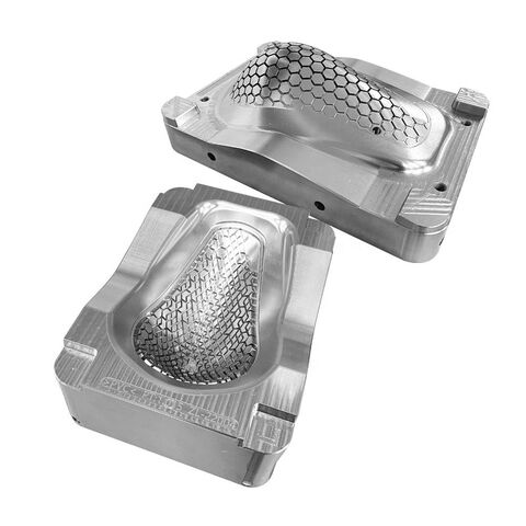
A: STEP (Standard for the Exchange of Product Data) is a newer, more robust ISO standard that accurately represents 3D solid models and assemblies. IGES (Initial Graphics Exchange Specification) is an older standard focused on representing surfaces. STEP is almost universally preferred today as it is more reliable, less prone to translation errors, and supports more modern design data.
Q4: Do I need to provide both a 3D file and a 2D drawing?
A: Yes, it is considered best practice. The 3D model (STEP) is the master geometry. The 2D drawing (PDF) provides essential manufacturing information that is not easily conveyed in 3D, such as:
Critical dimensions and tolerances (especially GD&T).
Surface finish requirements (e.g., Ra 0.8).
Thread specifications.
Material specifications and heat treatment notes.
Post-processing requirements (e.g., anodize type, thickness).
Q5: How does GreatLight Metal ensure my design data is secure?
A: GreatLight Metal takes intellectual property protection seriously. They operate with data security protocols compliant with ISO 27001 standards for information security management. Client designs are handled under strict confidentiality agreements (NDAs), and secure, controlled digital systems are used throughout the production process to prevent unauthorized access or data leakage. You can learn more about their professional standards on their LinkedIn page{:target=”_blank”}.



















