
Voltage Regulator Enclosure Sheet Metal: How It Works
A voltage regulator enclosure is not just a box. Material, gauge, bend geometry and seam continuity decide whether the regulator survives heat, vibration and EMI. This page explains the mechanism behind each choice so you can judge a design before it is cut.
In this article
- 1
- 2
- 3
- 4
- 5
- 6
- 7
Why the enclosure is part of the thermal circuit
A linear regulator turns the voltage difference into heat. That heat leaves through the package, the tab, the interface pad and finally the enclosure wall. Sheet metal is the last thermal resistance in that chain, and it is often the one nobody calculates. A 1.5 mm aluminum wall spreads heat sideways far better than a 1.0 mm steel wall of the same footprint.
The mechanism matters more than the number on a datasheet. Aluminum 5052 conducts roughly 138 W/m·K; cold-rolled steel sits near 50 W/m·K. If the regulator dissipates 3 W inside a sealed 120 × 80 × 40 mm box, the wall material changes the steady-state case temperature by 8–12 °C. That difference decides whether you stay under a 105 °C rating or drift past it.
Ventilation changes the picture again. A perforated panel raises convective area but lowers shielding. Open area above roughly 30% of the panel starts to hurt EMI performance more than it helps thermal performance for a switching regulator. For linear regulators running below 2 W, passive conduction through a solid wall is usually enough.
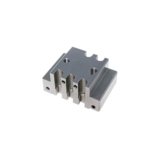
One practical rule: bond the regulator tab to the enclosure with a flat, machined boss rather than a bent flange. Bends introduce a radius and a spring-back angle, so contact pressure drops. A milled pad on a CNC-machined insert keeps the interface flat within ±0.05 mm and holds thermal paste thickness predictable.
- 1Gauge first1.2–2.0 mm aluminum covers most regulator boxes.
- 2Bond flatMachined pad beats a bent flange for contact pressure.
- 3Vent carefullyKeep open area below 30% if EMI matters.
Material and gauge: the trade between weight, stiffness and corrosion
Aluminum 5052-H32 is the default for regulator enclosures that see moisture or salt. It bends cleanly at a 1t inside radius, resists stress corrosion cracking and takes a chemical conversion coating before powder coat. Aluminum 6061-T6 is stiffer and machines better, but it cracks if you bend it tight across the grain, so keep the inside radius at 2t or more.
Cold-rolled steel grades such as SPCC and SECC cost less per kilogram and give higher stiffness per unit thickness. SECC carries a zinc layer that handles indoor condensation without extra coating. The penalty is weight and rust at cut edges. Any laser-cut or punched edge on steel needs a coating step, otherwise the first humid week starts the corrosion that shows up as a field return.
Stainless 304 works for chemical plants and washdown areas. It is three times heavier than aluminum and roughly three times harder to form, so tooling wear and bend tonnage climb. Stainless 316L adds molybdenum for chloride resistance. Use it only where chlorides are actually present; otherwise you pay for alloy you do not need.
Gauge choice follows stiffness, not habit. For a 200 mm wide panel, 1.5 mm aluminum deflects about 2.5 times more than 1.5 mm steel under the same load. If the enclosure carries a heavy transformer, step up to 2.0 mm aluminum or add a hemmed edge instead of chasing a thicker sheet everywhere.
- 15052-H32Best forming and corrosion balance for outdoor boxes.
- 2SECCCheap stiffness; coat every cut edge.
- 3316LOnly where chlorides are real.
Seam continuity: where shielding really lives
Shielding effectiveness comes from the current path, not the sheet itself. A solid panel blocks a field, but the moment that field finds a slot, a seam or an unbonded overlap, it couples through. A 25 mm long slot in a 1.5 mm wall acts as an antenna above roughly 6 GHz; below that it leaks less, but a switching regulator at 100 kHz to 2 MHz still radiates harmonics that a long seam will pass.
The fix is electrical continuity across every joint. Options include conductive gaskets, fingerstock channels, and a tight overlap with spot welds or rivets spaced every 20–25 mm. Paint and anodize are insulators. If you powder coat the outside, mask the mating flanges or use a conductive finish such as chromate conversion or conductive anodize on the inside faces.
Hole size matters as much as seam length. A round hole smaller than one-twentieth of the wavelength behaves as a poor radiator. For a 100 MHz harmonic that means keeping apertures under 15 mm. Cooling slots are usually longer than that, so orient them across the current path and keep the slot width narrow.
Grounding is the last link. A single-point ground at a painted flange gives you a capacitor, not a conductor. Bring the shield ground to a bare, masked area and bond it with a serrated washer or a dedicated stud. We check continuity across the assembled box with a milliohm meter before shipment when the drawing calls for it.
- 1Weld spacing20–25 mm along every lapped seam.
- 2Mask flangesCoating on mating faces breaks the shield.
- 3Slot ruleKeep apertures under λ/20 for the worst harmonic.
Bend radius, relief and the details that decide yield
Sheet metal design for a regulator enclosure lives or dies on bend geometry. The inside radius should sit between 0.5t and 1t for aluminum and 1t to 2t for steel. Go tighter and the outer fibers crack; go wider and spring-back grows, so the flange angle wanders. A press brake with a controlled back gauge holds flange length within ±0.15 mm; that is enough for a lid that seats without a fight.
Add a bend relief at every corner where a flange meets a wall. Without a relief, the material tears at the intersection and the crack runs into the panel. A relief of 1t wide and 1.5t deep removes the stress riser. The same logic applies to a hemmed edge; a hem adds stiffness and hides the sharp edge, but it needs a 3t flat length to close cleanly.
Hardware placement drives the rest. Pressed-in nuts, standoffs and clinch studs need a flat land at least 1.5 times the hardware diameter away from any bend. Put a nut too close and the bend pulls the hole out of round, so the screw will not start. Plan the flat pattern with 0.5 mm clearance between the bend tangent line and the nearest hole edge.
Tolerances stack. Laser cutting holds ±0.1 mm on profile; bending adds ±0.2° per flange; welding pulls the assembly another 0.3–0.5 mm depending on heat input. If the lid must line up with a connector cutout, dimension from a common datum and expect the total stack to land within ±0.5 mm. Anything tighter needs a machined interface plate.
- 1Inside radius0.5t–1t aluminum, 1t–2t steel.
- 2Bend relief1t wide, 1.5t deep at every corner.
- 3Hardware landKeep 1.5 × diameter from the bend.
Finishing and sealing: the boundary between indoor and outdoor use
Finishing sets the service life. For indoor control cabinets, a 60–80 μm powder coat over a conversion coating gives good scratch resistance. For outdoor or marine boxes, add a chromate conversion layer under the powder; that combination is what carries salt-spray performance past 1,000 hours when the coating stays intact. Bare aluminum alone will pit within weeks near the coast.
Sealing is a separate decision. An IP54 enclosure needs a gasket and a controlled flange flatness, usually better than 0.3 mm across the joint. An IP67 box needs a continuous gasket groove, uniform bolt spacing and a lid stiff enough that it does not bow between fasteners. Bolts every 40–50 mm on a 2.0 mm lid usually hold the compression the gasket needs.
Conductive requirements change the finish plan. If the enclosure is also an EMI shield, the inside faces stay bare or get a conductive coating, while the outside gets cosmetic paint. Masking adds a step, but skipping it means the shield is broken at every screw. Laser marking handles labels and ratings; keep character height at 1.5 mm or more so it stays legible after coating.
The wrong finish choice rarely fails at the bench. It fails in the field, after the enclosure has seen humidity, salt fog and thermal cycling. Match the finish to the actual environment the regulator will live in, not to the environment of the assembly line.
- 1IndoorConversion coat plus 60–80 μm powder.
- 2OutdoorAdd chromate under powder; seal the flange.
- 3EMI boxesMask mating faces, keep them conductive.
How the part moves from flat pattern to finished box
A voltage regulator enclosure typically runs through laser cutting, punching, deburring, bending, welding or riveting, then finishing. Each step adds error, and each step can lock in the next. Cut a flat pattern with the wrong bend allowance and no amount of careful bending saves the box; the flange lands short and the lid will not close.
Laser cutting handles the profile and the ventilation pattern in one pass, holding ±0.1 mm. For high volumes, a turret punch with a dedicated die cuts cycle time and keeps hole positions repeatable. Deburring follows; a sharp burr under a gasket becomes a leak path once the lid is torqued down.
Bending sets the geometry. A CNC press brake with angle measurement holds ±0.2° per flange. Welding, where needed, is TIG for thin stainless and spot or projection welding for steel boxes. Heat input pulls the part, so weld after the critical bends or plan a post-weld straightening pass.
Finishing and assembly close the loop. Holes tapped or hardware pressed before coating keep threads clean; threads cut after coating lose the corrosion protection on the cut. We run 100% inspection before shipment and can supply material certs, dimensional reports and coating thickness readings on request.
- 1CutLaser ±0.1 mm, punch for volume.
- 2BendCNC press brake, ±0.2° per flange.
- 3Finish lastCoat after forming, not between steps.
Enclosure sheet metal choices by requirement
Pick the row that matches your worst-case condition, not the average.
| Requirement | Material | Wall thickness | Notes |
|---|---|---|---|
| Lightweight, indoor | Aluminum 5052-H32 | 1.2–1.5 mm | Easy forming, good heat spread |
| High stiffness, low cost | Steel SECC | 1.0–1.5 mm | Coat every cut edge |
| Salt or washdown | Aluminum 5052 or 316L | 1.5–2.0 mm | Chromate under powder |
| Strong EMI shield | Steel SECC or aluminum | 1.5 mm | Weld seams every 20–25 mm |
| Heavy transformer load | Aluminum 6061-T6 | 2.0–3.0 mm | Machined pad for mounting |
| Chemical exposure | Stainless 316L | 1.5–2.0 mm | Higher bend tonnage, 2t radius |
Pick the material from the environment, not the drawing
If the regulator lives indoors and dissipates under 2 W, 1.2 mm aluminum 5052 with a conversion coat is enough. If it faces salt, washdown or a hard EMI limit, step to 1.5 mm 5052 or SECC with welded seams and a masked conductive flange. Stainless 316L only pays off where chlorides are actually present.
Common questions
How thick should a voltage regulator enclosure wall be?
Most boxes land between 1.2 mm and 2.0 mm. The number follows stiffness and heat spread, not a standard. A 200 mm wide panel in 1.5 mm aluminum deflects roughly 2.5 times more than the same panel in 1.5 mm steel.
If the box carries a transformer or a heavy heat sink, go to 2.0 mm aluminum or add a hemmed edge before adding thickness across the whole part.
Can a powder-coated enclosure still block EMI?
Not on its own. Powder coat and anodize are insulators, so a painted flange breaks the shield at every joint. Mask the mating faces or use a conductive finish such as chromate conversion or conductive anodize on the inside.
Check continuity across the assembled box with a milliohm meter after coating. That is the only way to know the seam still conducts.
What bend radius should I put on the drawing?
Use an inside radius of 0.5t to 1t for aluminum and 1t to 2t for steel. Tighter radii crack the outer fibers; wider radii increase spring-back and make the flange angle harder to hold.
Add a bend relief 1t wide and 1.5t deep at every corner where a flange meets a wall. Without it, the tear starts at the intersection and runs into the panel.
When do I need welding instead of rivets?
Weld when the seam must carry current for shielding or when the joint sees vibration. Spot or projection welding suits steel boxes; TIG suits thin stainless. Space welds every 20–25 mm along the lap.
Rivets work for low-volume builds and for joints that do not need electrical continuity. They are faster to assemble but they do not seal, and they loosen under sustained vibration.
How do I keep the lid and the connector cutout aligned?
Dimension both features from a common datum and accept a stack of about ±0.5 mm. Laser cutting holds ±0.1 mm, bending adds ±0.2° per flange, and welding pulls another 0.3–0.5 mm.
If the connector must sit within ±0.2 mm, mount it on a separate machined plate and bolt that plate to the sheet metal box. The sheet metal then only has to hold position, not define it.
Does anodizing hurt heat dissipation?
Clear anodize adds a thin oxide layer that actually helps radiation slightly and does not block conduction through the wall. Hardcoat anodize is thicker and more insulating, so it can add a small thermal resistance at the interface.
For a regulator running near its limit, keep the bond pad bare or use a conductive finish there, and let the rest of the box carry the cosmetic coating.
Send your enclosure drawing for a DFM review
We quote sheet metal and CNC work from one shop, review the flat pattern and bend reliefs, and return a quotation with free DFM analysis within 12 hours.
12-hour quote100% inspectionNo minimum order quantity
More from GreatLight
We publish setup notes, tooling trials and inspection data from the factory floor.











