1.Preface
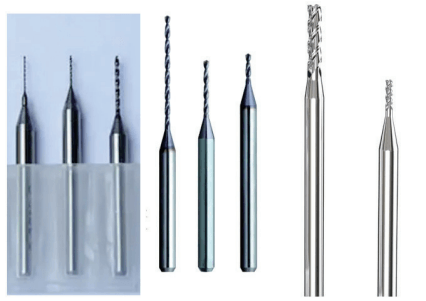
The small diameter strawberry illustrated in Figure 1 is in cemented carbide or fast steel. The diameter of the cutting edge is very small (φ0.1 ~ φ1.0 mm) and the length can reach 20 mm. And the secondary cutting surface of the strawberry must be rectified. The batch of products is important and the precision requirements are high. In real production, traditional processes are used and elastic pliers are generally used to tighten small diameter tools.[1]. First of all, since the tightening force of the elastic pliers is not easy to control, if the clamping force is too large, tightening damage will occur easily; If the clamping force is too low, the tool will easily become a way and loosen. Second, due to the short length of the handle of the small diameter tool held by the sleeve, the overhanging part of the tool is easily inclined, which causes an imprecise positioning. Finally, if only the stem of the tool is tight and the main and secondary surfaces of the tip of the tool are grinded, the tool will be affected by an unbalanced grinding force due to the high appearance ratio of the ‘Small diameter tool and insufficient rigidity of the tool. Produce a flexion deformation[2]. This will seriously affect the quality and efficiency of sharpening tools. How to solve the above production problems and develop a tightening device capable of effectively and stable tightening so small diameter tools is an urgent technical problem that must be resolved.
Figure 1 Small diameter strawberry
The difficulties of this project include the following points.
1) Due to the large number of product specifications, it must be adapted to the tightening of different specification bars by replacing the tightening tools of different specification.
2) Small diameter bars are easy to loosen or pinch, so they must be able to provide a reasonable and stable tightening force and precise positioning accuracy.
3) This tightening mechanism adopts a vertical tightening method when loading and unloading materials, in order to avoid interference, the upper and lower tightening parts must be shifted in the horizontal direction.
4) In order to adapt to the requirements of products of different specifications, the base of the cabinet must be designed to be adjustable in height.
5) In order to adjust the horizontal position of the base of the cabinet, it must be able to slide horizontally to facilitate the adjustment of the horizontal position of the base of the cabinet.
2. Structure of the vertical tightening mechanism of the bar
In response to the above problems, the author’s company has developed a vertical tightening mechanism for small diameter bars. The real object is illustrated in Figure 2, the transverse section is illustrated in Figure 3 and the 3D structure is illustrated in Figure 4.

Figure 2 Real vertical clamping mechanism of small diameter bars

Figure 3 Cup view of the vertical tightening mechanism of the bars of small diameter

Figure 4 3D structure of the vertical tightening mechanism of the bars of small diameter
1) As shown in Figure 4, the tightening part of the nucleus of the vertical tightening mechanism of the small diameter bars includes a upper clamping arm, a lower tightening arm, a hollow base and a upper plate installed in a fixed manner -Disfall. The base consists of multiple bonding plates. Four vertical bonding plates are fixed on the periphery of the fixed base plate to form a hollow basic box.
2) As shown in Figure 3, one end of the lower tightening arm is fixed on the basis of the base, and the stability of the fixed connection between the lower tightening arm and the base must be ensured. The other end of the lower tightening arm is equipped with a tightening slot in order to be able to tighten different specification bar materials, the end of the upper clamping slot of the lower tightening arm is equipped with a support of Removable connection, which is fixed by a loop structure or screws. In this way, the card holder can be removed and replaced from the lower tightening arm, and the card slot is provided on the card holder. By replacing the card holder with different specifications, it is appropriate. Tightening bar materials of different specifications. In order to improve the accuracy of tightening and guarantee the tightening force, the transverse shape of the card slit is generally designed to be V -shaped.
3) As shown in Figure 4, there is an upper tightening arm corresponding to the lower tightening arm, and the tightening piece on it corresponds to the slit. Similarly, in order to adapt to the tightening of bars of different specifications and quickly adjust the size of the tightening part, the tightening part is also designed as a detachable mechanism, generally using screws or loop structures. In the case of application, the end surface of the tightening item used for tightening is a flat surface when the flat surface comes into contact with the bar, a contact line can be formed, which provides a force of sufficient tightening to tighten the bar.
4) As Figure 4 shows, there is a mobile channel on the upper plate of the upper part of the base of the box. The guide block located in the base is designed as a convex structure. The upper surface of the guide block is equipped. A mounting part that crosses the mobile channel and can slide along the mobile canal, the mounting part being fixed to the upper tightening arm. There is a mobile space between the shoulder of the guide block and the upper plate. The guidance block can make a back and forth movement in the vertical direction compared to the upper plate under the action of an external force. The guidance block leads to the upper tightening arm to move upwards. thus making the tightening of the upper tightening arm. The room and the card holder are separated in the vertical direction.
5) As Figure 5 shows, there is an elastic element between the upper plate and the guide block which causes the guidance block down. The guide block has a convex structure. The shoulder of the guidance block has a borgne hole for the. elastic element to insert.[3]Place it in the borne hole, one end of the spring presses against the bottom of the borgne hole and the other end of the spring presses against the lower surface of the upper plate. The spring is in a compressed condition from the upper plate. is a fixed part and the guide block is a mobile part, the guide block is in the spring position, it moves downwards under the action of an elastic force, and because the mounting part on the block guidance is fixed fixed to the upper tightening arm, it leads to the tightening element to move to the slot, so that the tightening part firmly tightens the bar placed in the slit.

Figure 5 positions of the upper block and guidance block
6) In real production, if the tightening mechanism that opens and closes from top to bottom is simply used,[4]will inevitably pose the problem of the difficulties of loading materials. If the tightening part and the slit are only separated in the vertical direction, although the tightening force between the tightening part and the slot is eliminated and the bar can be placed in the slit, there is a pliers -Dussess of the slit. Holding parts cannot be placed. Placed in the slot from top to bottom. The bar can only be inserted into the slit in the horizontal sense, which will undoubtedly cause loading difficulties.
7) The base of the box is designed with a drive mechanism that leads to the guide block to move upwards and slip into the horizontal direction. In reference to Figures 3 and 4, the sliding drive block is located under the guide block, and a coach who can slide back and forth in the horizontal direction is installed outside the base of the box. The coach can be a conventional racing engine or cylinder. . The pilot’s telescopic rod is inserted into the base and connected fixed to the cursor, so the pilot can drag the cursor into the horizontal direction compared to the base.
8) As shown in Figure 6, the upper surface of the cursor is in close contact with the lower surface of the guide block. The upper surface of the cursor has a first guidance slope which is oblique upwards. The guidance block is provided with a third guidance slope which is complementary to the first guidance slope. The drive mechanism also includes a limit slot on the lower surface of the guide block and a limit column on the upper surface of the cursor. The limit column is inserted in the limit slot, and the limit column can make a back and forth movement in the horizontal direction along the cursor. Limited location. In practical applications, the drive mechanism can first separate the tightening element from the slit in the vertical direction, then cause the tightening element and the slit so that they shift in the horizontal direction, thus resolving effectively the problem of loading interference.

a) tight state b) separate condition
Figure 6 Position of the cursor and the guide block
9) Refer to Figure 4. The lower surface of the base of the housing is attached to the mounting plate. There is a bearing in front of the mounting plate. There is an adjustment engine on the rear side of the mounting plate. The adjustment engine crosses the mounting plate and is located under the bearing. The mounting plate is designed with an adjustment hole for the passage of the engine output. The adjustment hole is a long U -shaped hole. The output shaft passes through the adjustment hole and can slide in the height direction. The output shaft of the adjustment engine is fixed to an eccentric wheel, and the eccentric wheel is in contact with the exterior ring of the bearing. By setting the eccentric and the bearings, the position of the base in the height direction is adjusted.
10) Refer to Figure 4. In order to facilitate the adjustment of the base position in the horizontal direction, the lower surface of the mounting plate is fixed with a shot seat. The lower surface of the shot seat has a spawn tail. groove. There is an assembly seat under the Aronde tail seat. The top of the assembly seat faces. The ball -tail block is formed by exceeding from the top, and the ball -tailed block is inserted into the spawning tail groove from the base in the balloons and slides in the horizontal direction. To adjust the position of the tightening mechanism in the horizontal direction.
3. Principle of operation of the vertical tightening mechanism of the bars of small diameter
The work process of this vertical barrel tightening mechanism: when unloading and tightening, the tightening part and the slit are aligned in the vertical direction and are closer to each other, and the spring is in a Pop-up condition, causing the guidance block to move down and cause the fixed installation. The bottom tightening part keeps the bar to be treated, the telescopic stem of the coach is extended, the second guidance block guidance slope is closely adapted to the first guidance slope of the sliding block. , and the limit column is against the right side slit (see Figure 6a).
When unloading the materials, the driver starts, the driver’s telescopic rod retracts over a certain distance and causes the cursor to slide to the left in the horizontal direction. With the cooperation of the first guidance slope and the second guidance slope, the cursor slides to the left. To the left with respect to the guide block, the limit column on the cursor moves along the limit groove. By sliding to the left, the sliding block sliding to the left results in a movement towards the top of the guide block, the spring is compressed and the movement up of the guidance block will cause the upper tightening arm installed fixed On the mounting part to move upwards, causing the tightening part and the slit separate in the height direction, at this time the spring is in a compressed condition.
The driver’s telescopic stem continues to retract when the limit stem resists the left wall of the limit slot, the driver’s telescopic stem continues to retract, causing the cursor to push the guidance block to slide together to the left horizontal. direction, thus making the installation fixed. The upper tightening arm on the mounting part moves to the left for. By shifting the tightening part and the slit in the horizontal direction, the external device can fall vertically to grab the finished bar material in the slit. This also prevents the tightening part from preventing external equipment from freeing the stem in the vertical direction. The material is placed in the slit to complete the opening action of the tightening mechanism.
When loading, the manipulator automatically places a material bar in the slit in the vertical direction. After that, the driver’s telescopic rod extends to the right and returns. The telescopic rod first causes the guidance block so that it retreats to the right. Horizontal direction, so the pliers aligns the support vertically with the card slot. During the sliding return of the guide block, the elastic organ (tightening spring) in the compressed state uses its own elastic force to cause the guidance block down, so that the tightening organ moves to the low and cooperate with the slit to hug the bar. the tightening tightening action of the tightening mechanism.
When the base must be high or lowered, the adjustment engine can be started and the output shaft of the adjustment engine runs to train the heart wheel. Since the eccentric and output shaft of the adjustment engine are adjusted in an eccentric way, the eccentric pushes against the bearing, causing the change of position of the base, thus adjusting the position of the tightening mechanism in the direction of the height to adapt it to more working conditions.
4.Conclusion
The vertical tightening mechanism of the small diameter bar has a simple and reliable structure. He squeezes the part of the upper from the bar from top to bottom and helps the pliers tighten the handle of the bar. The tightening is more stable and faster, and the assembly time is shortened. Once tight, it improves work efficiency. It adopts the slope change in mechanical parts combined with the elastic pressure adjustment training mechanism to provide a stable and reliable bar clamping force. And by replacing the V -shaped groove supports from different specifications, it can adapt to the tightening of bar materials of different specifications. The tightening accuracy is high and the tightening force is uniform and stable. When unloading materials, the tightening part and the slit are not only loosened vertical, but also offset from a certain position in the horizontal direction, which effectively solves the problem of loading interference and guarantees automated production on a large scale.
Currently, this vertical bars tightening mechanism has been used on a large scale in the author’s company, effectively improving production efficiency, making the degree of automation reliable and stable and guaranteeing precision and product yield.
Daguang focuses on providing solutions such as precision CNC machining services (3-axis, 4-axis, 5-axis machining), CNC milling, 3D printing and rapid prototyping services.


