
UAV Compass Sensor Mounts Rapid Prototype
A magnetometer mount is not a bracket. It is a metrology part that happens to hold a sensor. This page explains what makes a UAV compass sensor mounts rapid prototype succeed, which materials stay non-magnetic, and how machining decisions affect heading accuracy before you cut metal.
In this article
- 1
- 2
- 3
- 4
- 5
- 6
Why a UAV compass sensor mounts rapid prototype is a metrology problem
A magnetometer reads the Earth's field, which is weak. Total field strength is roughly 25 to 65 μT depending on latitude, while a small steel screw can produce a local field of several hundred μT at 10 mm. That ratio is why a compass mount prototype fails for reasons that never show up on a CMM report.
The heading error a magnetometer sees depends on hard iron and soft iron effects. Hard iron is a fixed offset from permanently magnetized material. Soft iron is field distortion from permeable material, and it changes with the aircraft's orientation relative to the field. Both are geometry and material problems, not firmware problems.
So the UAV compass sensor mounts rapid prototype phase is not a shape trial. It is a test of whether the chosen alloy, heat treatment, and finishing sequence produce a part whose magnetic signature stays inside the calibration budget of the flight controller.
This matters most when the compass sits near motors, ESCs, or carbon fiber booms with conductive layups. In those builds, a mount that passes on the bench can still shift heading by 3 to 8 degrees in flight because eddy currents in nearby conductors change with attitude.
- 1Hard ironFixed offset from magnetized screws, inserts, or tool marks.
- 2Soft ironField distortion from permeable alloys; varies with heading.
- 3Eddy currentsTime-varying fields from conductive parts moving in the field.
Non-magnetic material choice for drone compass mounts
The default for a first article is aluminium 6061-T6. It machines clean, holds thin walls, has no meaningful ferromagnetic response, and is easy to anodize. For a UAV compass sensor mounts rapid prototype that will see bench and hover testing, 6061-T6 covers most cases. If stiffness per gram matters more, 7075-T6 is the next step, though it is less weldable and more prone to stress corrosion if not finished properly.
Titanium TC4 (Ti-6Al-4V) is essentially non-magnetic in the annealed and mill-annealed condition and gives roughly 60 percent higher specific stiffness than aluminium. The trade-off is machining cost and thermal growth. Titanium conducts heat poorly, so cutters run hot and thin walls deflect. Rough, stress-relieve, then finish is not optional here.
PEEK and carbon fiber reinforced PEEK are attractive when you need low thermal conductivity and near-zero magnetic signature, but they bring their own constraints. PEEK is hygroscopic to a small degree, has a coefficient of thermal expansion several times that of aluminium, and is expensive in bar stock. For a prototype, that cost is usually acceptable.
Avoid 400-series stainless, any martensitic grade, and 17-4PH if the part sits within 30 to 50 mm of the magnetometer. Even weakly magnetic grades create offsets that change with heat treatment. If corrosion resistance is mandatory, use 316L and verify with a gaussmeter before assembly.
- 16061-T6Default choice. Non-magnetic, machines well, anodizes cleanly.
- 27075-T6Higher stiffness. Better for thin cantilever arms.
- 3Ti-6Al-4VNon-magnetic, high specific stiffness, harder to machine.
- 4PEEKLow conductivity, low magnetic signature, high CTE.
Machining rules that keep the compass mount dimensionally stable
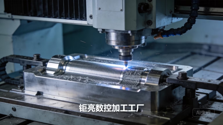
Thin-wall geometry is where most rapid prototypes go wrong. A wall under 1.0 mm in aluminium will move under clamping and cutting forces unless the setup supports it. On 5-axis machines we rough with 0.3 to 0.5 mm radial stock, then semi-finish with a smaller stepover before the final pass. The point is to remove the bulk of the material while the part is still thick and stiff.
Stress relief matters more than most engineers expect. Aluminium plate carries residual stress from rolling. When you machine one side, that stress rebalances and the part bows. For a prototype with a 0.05 mm flatness callout, a stress-relief cycle between roughing and finishing keeps the final geometry predictable.
Tool marks are not just cosmetic on a compass mount. A rough surface can trap ferromagnetic contamination from handling or from a previous steel job. Parts that touch a magnetometer should be machined on tooling dedicated to non-ferrous work, or cleaned thoroughly and checked with a gaussmeter.
Mechanical decoupling is a design decision you can only validate by machining. Slots, flexures, and isolated bosses let the mount absorb vibration without transferring strain to the sensor. A prototype is the cheapest place to test whether a 0.5 mm wide slot actually decouples the compass from frame bending, or just creates a weak point.
- 1Rough, relieve, finishTwo-stage material removal controls distortion.
- 2Dedicated toolingKeep ferrous fixtures away from non-magnetic parts.
- 3Clean before assemblyRemove chips and contamination; verify with gaussmeter.
How to verify a compass mount prototype before flight
Bench testing catches most magnetic problems. Put the mount in the same orientation it will see in the aircraft, then sweep the assembly through 360 degrees of yaw on a non-magnetic turntable. Compare the magnetometer output against a reference. A clean part shows a smooth sine wave. A part with hard iron shows a DC offset; a part with soft iron shows an ellipse rather than a circle.
The second test is a vibration sweep. Mount the sensor, run the motors through their throttle range, and watch heading noise. If heading wanders more than 1 to 2 degrees at hover throttle, the mount is coupling vibration into the sensor. That is a mechanical fix, not a filter fix.
For thermal stability, cycle the assembly between -20 °C and 60 °C and re-check heading. Aluminium and PEEK move differently, so a PEEK mount may need a larger clearance around the sensor or a different fastening strategy. This is exactly the kind of thing a rapid prototype is meant to expose.
Document everything. The calibration offsets you measure on the prototype become the baseline for the next iteration. If you change material or finish, expect the offsets to change.
- 1Yaw sweepLook for offset and ellipse distortion in the magnetometer output.
- 2Vibration sweepHeading noise above 1–2 degrees means mechanical coupling.
- 3Thermal cycleCheck for CTE mismatch between mount and sensor.
Step-by-step: from CAD to a flight-ready compass mount prototype
Typical sequence for a single prototype. Adjust parameters for your material and geometry.
- 1Review DFM and materialConfirm alloy, wall thickness, and which faces are datums. Flag any feature under 0.8 mm.
- 2Rough machineLeave 0.3–0.5 mm radial stock. Use adaptive clearing to keep tool load steady.
- 3Stress reliefThermal cycle if flatness matters. Skip only for non-critical brackets.
- 4Semi-finish and finishReduce stepover, then take a light final pass at Ra 0.8–1.6 μm.
- 5Deburr and cleanRemove all burrs. Clean in a non-ferrous area, then check with a gaussmeter.
- 6Inspect and documentMeasure critical features to ±0.005 mm. Report on request.
- 7Finish and markAnodize, bead blast, or leave as-machined. Laser mark if traceability is needed.
Material comparison for UAV compass sensor mount prototypes
Values are typical for prototype quantities. Magnetic response assumes annealed or T6 condition.
| Material | Magnetic response | Best for | Watch out for |
|---|---|---|---|
| Aluminium 6061-T6 | Non-magnetic | General prototype, first flight | Thin walls under 1.0 mm deflect |
| Aluminium 7075-T6 | Non-magnetic | Stiff cantilever arms | Stress corrosion without anodize |
| Titanium Ti-6Al-4V | Non-magnetic | High vibration, low mass | Heat buildup, cutter wear, warping |
| PEEK (unfilled) | Non-magnetic | Low conductivity, RF transparency | CTE roughly 3–5× aluminium |
| 316L stainless | Weakly magnetic after cold work | Corrosive environments | Verify with gaussmeter after machining |
| 17-4PH stainless | Magnetic after aging | Not recommended near magnetometer | Permanent offset after heat treat |
| Magnesium AZ31B | Non-magnetic | Ultralight frames | Corrosion, flammability controls |
When to choose which material
For a first-flight UAV compass sensor mounts rapid prototype, use aluminium 6061-T6 unless weight or vibration demands otherwise. Move to titanium only when you have measured a vibration or stiffness problem that aluminium cannot solve. Use PEEK when conductivity near the sensor is the limiting factor, and accept the thermal trade-off.
Common questions about UAV compass sensor mounts rapid prototype
Can I 3D print the first iteration of a compass mount?
You can, but treat it as a fit check only. Nylon and ASA are non-magnetic, but they are not dimensionally stable enough for a sensor that needs repeatable heading.
Use the printed part to check bolt patterns and cable routing, then machine the flight version from aluminium or PEEK.
How close can a steel screw be to the magnetometer?
There is no universal number. It depends on screw size, alloy, and whether it is magnetized. A small 304 screw at 20 mm may be fine; an M4 steel screw at 5 mm usually is not.
Measure with a gaussmeter at the sensor position after assembly. If the field changes by more than a few μT when you rotate the screw, move it or switch to brass or nylon.
Does anodizing affect the magnetic signature?
Type II and Type III anodizing on aluminium do not add ferromagnetic material. The oxide layer is non-magnetic.
The risk is contamination from the anodizing rack or from handling. Ask for parts to be processed and packed away from ferrous tooling.
What tolerance should I specify for the sensor mounting face?
Flatness and position matter more than the overall dimension. A common callout is 0.02 to 0.05 mm flatness on the sensor face and ±0.05 mm on mounting hole position.
Our machines hold ±0.005 mm when the geometry allows it, but tighter than needed adds cost without helping heading accuracy.
How fast can I get a machined compass mount prototype?
Quotation and DFM analysis come back within 12 hours. Production can start within 24 hours after that, and parts typically ship in 3–5 days.
Lead time depends on material availability and finishing. Titanium and PEEK may need a day or two longer for stock.
Can you machine a mount that isolates the compass from frame vibration?
Yes. We machine flexures, isolation slots, and separate bosses as one part or as an assembly.
Send the CAD and tell us the vibration band you are worried about. The DFM review will flag features that are too thin or too deep to cut reliably.
Start your compass mount prototype
Upload your CAD and get a quote with DFM feedback within 12 hours. From one prototype to 10,000+ parts, with no minimum order quantity.
12-hour quote100% inspectionNDA on requestNo minimum order quantity
GreatLight on social
We publish setup notes, tooling trials and inspection data from the factory floor.











