In the metal cutting process, cutting vibration is inevitable. How to reduce cutting vibration is a topic that people in the industry have studied. During processing, the selection of different machine tools, accessories and cutting tools will cause workpiece vibration. This article only analyzes the causes and solutions of processing vibration from the perspective of metal cutting tool structure.
1 Preface
During the metal cutting process, the cutting vibration will produce vibration patterns on the surface of the workpiece, which will lead to a reduction in the machining precision and surface quality of the workpiece. Excessive vibration can easily cause fasteners to loosen, reduce machine tool accuracy and tool life, and even damage tools. Once a safety accident occurs, it will have irreversible effects.
2 Analyze the influence of tool structure on cutting vibrations
2.1 Effect of tool tip fillet on cutting vibrations
When selecting a tool, you typically choose an insert with a large rounded corner. The lifespan of an insert with a large rounded corner is longer. However, when finishing, the tool tip fillet should be selected based on the cutting allowance. the ideal tool life cannot be achieved; the rounded corner if it is large, it will produce vibration, commonly known as “the knife cannot be pressed”.
(1) The influence of tool nose corner radius on turning vibration is as follows.
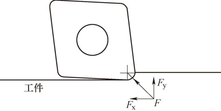
As shown in Figure 1, when the back engagement amount ≈ the tool tip fillet radius, the axial force Fx ≈ the radial force Fy, and there is a possibility of vibration at this time .
Figure 1 Back cut amount ≈ tool tip fillet radius
As shown in Figure 2, when the back engagement degree is less than the tool tip fillet radius, the axial force Fx is less than the radial force Fy. At this stage, the cutting force is mainly radial force, which is subject to vibration and. “I can’t hold it.”

Figure 2 Back Cutting Amount<Tool Tip Fillet Radius
As shown in Figure 3, when the rear engagement degree of the tool > the fillet radius of the tool tip, the axial force Fx > the radial force Fy, at that time, the force of Cutting is dominated by axial force and machining is generally stable.

Figure 3 Back Cut Amount > Tool Tip Fillet Radius
Therefore, when selecting an insert, you should choose a tool nose radius with a degree of back engagement > tool tip fillet radius, to ensure the maximum axial cutting force.
A customer processes spindle shaft parts and outsources rough machining. Rough machining leaves only 0.15 mm margin for processing. As shown in Figure 4, a R0.4mm fillet blade. is used. There are vibration marks during processing. After eliminating the processing parameters and other reasons, it is determined that the cause of the vibration is that the amount of cutting on the back is too small. Replace it only with CCMT060202 blade and select R0.2mm fillet blade as shown in Figure 5. If other processing parameters remain unchanged, the vibration marks will disappear and the processing requirements will be met.

Figure 4 Processing effect of R0.4mm fillet inserts

Figure 5 Processing effect of R0.2mm fillet inserts
(2) The impact of tool tip fillet on milling vibration. The structure of milling cutters is more complex than that of turning tools, and many factors affect cutting vibration. Compared with other factors, the impact of tool tip fillet on vibration. is smaller.
As with turning, if machine tool power and torque conditions permit, choosing a larger fillet insert during roughing can achieve higher tool life and efficiency. When finishing, R0.4mm fillet inserts are generally used, which can basically meet most processing conditions.
It should be noted that when the amount of exposure of the knife on the back is too small, in addition to the vibration caused by the above-mentioned “unable to hold the knife” situation, scratches will also appear, but they are not caused by vibrations. .
Cutters with replaceable inserts have manufacturing tolerances and there is no guarantee that the inserts installed on the cutter body will be absolutely the same height. The error between the highest and lowest points of the blade can even reach more than 0.03mm. Therefore, when the amount of backcut is very small and cannot be adjusted, an axially adjustable face mill or precision solid carbide milling cutter can be used (see Figure 6).

Figure 6 Mapal Power Mill axially adjustable precision grinding wheel
2.2 Effect of main deflection angle on cutting vibration
The main deviation angle is the angle between the cutting edge and the feed direction. This parameter not only affects the chip shape and cutting edge length, but also affects the direction of cutting force and has a great impact on cutting vibration.
(1) The effect of deflection angle on turning vibration is shown in Figure 7. F is the total rotation force, Fx is the axial rotation force, and Fy is the radial rotation force. As the main deflection angle increases during turning, the tool. axis The greater the radial force, the lower the radial force and therefore the lower the risk of vibration.

a) Turning tool with 45° lead angle

b) Turning tool with 75° lead angle

c) Turning tool with 90° lead angle
Figure 7 Schematic diagram of the main turning tools in different angles
The radial force and axial force of a turning tool or boring tool with a rake angle of 45° are equal, and vibration is most likely to occur at this time. When selecting turning tools or boring tools, you should generally favor tools with a lead angle close to 90°. Especially when turning thin shafts or boring holes, tools with a lead angle of 90° should be selected as much as possible to reduce the radial. force and reduce the radial force. Get the best cutting results.
(2) The influence of the main declination angle on milling vibrations. Generally, the primary declination angle of a cutter has little effect on milling vibration. Only under special working conditions does the main declination angle have a greater impact on processing.
1) Processing of thin-walled parts. When processing thin-walled parts, it is best to use square shoulder cutters with an attack angle of 90°. The square shoulder milling cutter has the largest radial force and the smallest axial force during the milling process. It experiences low vertical pressure when milling thin-walled parts, which can minimize the occurrence of vibration.
2) Working conditions with long tool overhang. When milling with a long overhang cutter, the closer the main angle is to 90°, the greater the radial force during milling and the greater the vibration. When milling with a long overhang, a main angle milling cutter of 45° should be preferred, and the back engagement degree is <1mm, you can choose a round blade milling cutter.
2.3 Effect of number of teeth and tooth pitch of the cutter on cutting vibrations
The greater the power required during cutting, the greater the risk of vibration.[1]。
The formula for calculating net power is as follows

In the formula, Pc is the net power (kW); ap is the back cutting quantity (mm); ae is the cutting width (mm); vf is the feed speed (mm/min); N/mm2); fz is the feed per tooth (mm/z); n is the spindle speed (r/min) is the number of teeth (number).
Taking surface milling as an example, the milling power is proportional to the number of teeth. For the same diameter cutter, a 10-edged cutter requires twice the power of a 5-edged cutter. When selecting tools, you should not blindly pursue a high number of teeth for the sake of treatment effectiveness. You also need to determine if the machine tool and fixture can meet the power requirements.
Besides the number of teeth, the pitch of the teeth is also an important factor. The advantage of unequal pitch tools is that they can interrupt resonance, thereby improving stability. The effect is particularly evident on tools with large cutting widths and long overhangs.
During milling, if vibration occurs, multiple blades can be removed to reduce cutting power by reducing the number of teeth. It should be noted that if only a certain blade is removed, the next blade will carry twice the feed per tooth. It is necessary to remove every other blade so that the force exerted on each blade is uniform and the feed speed of each tooth is constant to achieve the ideal cutting effect.
2.4 Effect of cutting angle on cutting vibration
The rake angle of the tool is the angle between the cutting surface and the base surface. The cutting angle is not only divided into large and small, but also positive and negative. The larger the cutting angle, the lower the cutting force; the smaller the cutting angle, the greater the cutting force. Positive rake angle inserts are single-sided inserts with low cutting force but low blade resistance. Negative rake angle inserts have both single-sided inserts and double-sided inserts with 0° clearance angle, high cutting force and high blade strength. for intensive cuts.
(1) The influence of rake angle on vibration in turning is shown in Figure 8. If a negative rake angle insert is mistakenly used for finishing during cutting, it can easily cause vibration. If a positive rake angle insert is used for rough machining, it can easily cause vibration. the lifespan of the part will be short.
(2) The influence of rake angle on milling vibration is shown in Figure 9. The rake angle of the cutter is divided into axial rake angle and radial rake angle. The axial cutting angle affects the cutting shape and the direction of the cutting force, and the radial cutting angle affects the cutting power.[2]。
Select the cutting angle of the cutter according to the processing conditions and the precision of the workpiece. The characteristics of cutters with different cutting angles are as follows.
1) Double positive cutting angle milling cutter. Axial rake angle and radial rake angle are positive rake angle cutters. This type of milling cutter has low cutting force and smooth chip removal. It is suitable for machine tools with insufficient power and unstable clamping conditions.
2) Double negative cutting angle milling cutter. Axial rake angle and radial rake angle are negative rake angle cutters. This type of milling cutter is suitable for rough machining. It has great cutting force and is prone to vibration.
3) Positive and negative rake angle cutters. The axial rake angle is a positive rake angle and the radial rake angle is a negative rake angle. This is the most commonly used combination of cutters on the market.

a) Negative rake angle insert

b) Positive rake angle insert
Figure 8 Illustration of positive and negative rake angle inserts for turning tools

a) Radial rake angle b) Axial rake angle
Figure 9 Illustration of cutter cutting angle
2.5 Effect of tool tip angle on cutting vibration
Taking turning or boring as an example, as shown in Figure 10, the blade tip angles are generally 35°, 55°, 60°, 80°, 90°, and round inserts. The greater the angle of the tool tip, the stronger the blade, the greater the cutting force it resists, and the greater the likelihood of vibration. Among them, the circular blade has the highest vibration probability.[1]. Assuming that the main declination angle of the tool is the same, the larger the tool nose angle and the smaller the auxiliary main declination angle, the greater the probability of chip extrusion on the auxiliary cutting edge is greater, conversely, the smaller the angle of the nose of the tool; the larger the auxiliary main declination angle, the larger the gap, and the lower the probability of chipping, the lower the probability of vibration.

Figure 10: Tool tip angle diagram
2.6 Effect of tool aspect ratio on cutting vibration
The aspect ratio of the tool, i.e. the ratio of the length of the overhang to the diameter of the tool. Whether it is a turning tool, milling cutter or boring tool, aspect ratio is an important parameter that affects vibration.[2]The cantilever beam diagram is shown in Figure 11.

Figure 11 Schematic of the cantilever beam
The deflection formula of cantilever beam structure is as follows

In the formula, W is the deflection (mm); F is the cutting force (N); L is the length of the tool overhang (mm); E is the elastic modulus (MPa); inertia (mm4); D is the diameter of the tool holder (mm).
It follows from equations (3) and (4) that when the diameters are identical, the deflection is proportional to the cubic value of the length. When the length remains constant, the deflection is inversely proportional to the fourth power of the diameter. The tool clamped on the machine tool is a cantilever beam structure. Comparing the above formulas, when selecting tools, tools with short length, large diameter and small aspect ratio should be preferred.
When the length to diameter ratio must be large due to limitations in working conditions and part structure, the following three methods are generally used.
(1) To increase the rigidity of the tool holder, use heavy metal, carbide or vibration damping tool holder as the tool holder material according to the length/diameter ratio L/D, generally when L/D< . 4, ordinary steel tool holders are used; when 4<6, utilisez un porte-outil en métal lourd ou un porte-outil en carbure lorsque L/D>6, use vibration damping tool holder;
As shown in Figure 12, the same cutting parameters are used, the processing material is 45 steel, the tool length is 238mm, the tool diameter is 40mm, the ratio aspect L/D is about 6, the cutting speed vc=0.12 m/min, and the rear cutting quantity ap=1mm, the feed speed vf=143mm/min, the effect processing of vibration damping tool holder is obviously better than that of steel tool holder.

a) Processing effect of ordinary steel boring bars (with vibration marks)

b) Processing effect of vibration absorbing boring bars (no vibration marks)
Figure 12 Comparison of processing effects of different cutting body materials
(2) The guide bar support tool, as shown in Figure 13, is a crankshaft guide bar support tool. These tools are non-standard tools and are suitable for finishing holes. Depending on the design of the workpiece structure, the support is removed through the workpiece. own structure or the ring of the luminaire. This type of tool is commonly used in the automotive processing industry, such as engine blocks and cylinder heads.

Figure 13 Crankshaft Guide Bar Holder Tool
(3) Plunge milling is shown in Figure 14. The plunge milling cutter is fed axially like a drill bit. During cutting, the tool is mainly subjected to axial force and the radial force is weaker when the tool needs to be cantilevered at L./D>4, you can use plunge milling for cutting. rough machining. When using this method, you should be careful to choose a plunge milling tool with as many edges as possible. This will not only improve the effectiveness of treatment, but also maintain at least. one tooth cutting the workpiece during processing, to ensure the stability of processing.

Figure 14 Plunge milling diagram
2.7 Effect of tool interface on cutting vibration
The influence of the turning tool interface on vibration is detailed as follows.
1) Tightening method. The clamping method between the turning tool holder and the machine tool has a great influence on the formation of vibrations.[2]. Figure 15 shows the three most common situations where lathes clamp boring bars A, B, and C all use cylindrical boring bars. Among them, A uses an external clamping tool holder, which can achieve the greatest stability through full circumference clamping, and it is recommended that the effective clamping length be more than 3 times the diameter; B uses a side-mounted clamping tool holder; with one side It is pressed by bolts and the lower end is supported by a V-shaped block. It can be suitable for flat shank structure boring bars, but it is not suitable for flat shank structure boring bars with flat shank. The cylindrical shank boring bar is likely to produce vibrations; C also uses a side-fixed clamping tool holder, which is tightened by screws on both sides. This tightening method is not recommended. First of all, the tightening position of the screws may not be. clamped in the center of the boring bar. If there is a deviation in the position, the boring bar will be deformed due to the clamping force and the boring bar will be damaged during processing.

Figure 15 Schematic diagram of lathe clamping method
2) Clamping length. As shown in Figure 16, it is necessary to ensure that the effective clamping length is greater than 3 times the diameter to balance the cutting force.

Figure 16 Internal turning tool tightening diagram
2.8 Effect of milling tool interface on cutting vibration
For machining center machine tools, tool holders can be divided into overpositioning tool holders and non-overpositioning tool holders such as BBT, HSK, Capto, KM and big-plus tool holders, etc. and non-overpositioning tool holders such as JT, BT tool handle, etc.[3]Figure 17 takes the BT tool holder and the BBT tool holder as examples. For long overhang tools, the machine-tool interface is an important factor. When machining long overhangs, the effect of over-located tool holders is better than that of non-over-located tool holders.

a) Ordinary BT tool holder, there is a gap between the flange surface and the spindle end surface

b) Over-positioned BBT tool holder, there is no gap between the flange surface and the spindle end face. Figure 17 Comparison of BT tool holder and overpositioned BBT tool holder.
3 Conclusion
Many factors produce cutting vibrations during machining. Through the analysis of the tool structure, this paper draws the following five conclusions, which will play a positive role in solving the machining vibration problem.
1) Cutting force can be reduced by reducing the tool nose radius, using positive rake angle tools, and reducing the number of tool teeth.
2) Changing the main deviation angle and using the plunge milling method can change the cutting force in only one direction.
3) Boring bars with uneven tooth pitch and damping will destroy the natural vibration frequency of the cut.
4) The length to diameter ratio of the tool holder should be as small as possible and the tool rigidity can be increased by using heavy metal or carbide tool bodies.
5) Using guide bars to help support the tool, selecting an over-positioned tool holder, and selecting a smaller tool tip angle can improve stability during processing.
Daguang focuses on providing solutions such as precision CNC machining services (3-axis, 4-axis, 5-axis machining), CNC milling, 3D printing and rapid prototyping services.


