
Vibration damping mounts metal casting: how the part actually works
A cast mount is not just a bracket. Its ribs, walls, and mass distribution set how vibration moves from the actuator into the frame. This page explains the mechanism, the alloy and wall-thickness limits, and the machining steps that decide whether the mount holds its stiffness after assembly.
In this article
- 1
- 2
- 3
- 4
- 5
- 6
Where vibration damping mounts metal casting loses energy
A robot arm shakes for a simple reason. The servo accelerates a mass, the mass overshoots, and the frame rings at its natural frequency. A mount sits in that path. It does not remove energy by magic. It changes how the energy moves.
Cast metal gives you two loss paths that a solid billet cannot match. The first is geometry. Ribs, pockets, and varying wall sections put stiffness where the load is and remove mass where it is not needed. A lower moving mass at the same stiffness raises the natural frequency, which typically moves the resonance out of the servo bandwidth.
The second is material damping. Cast aluminum ADC12 and ductile iron both convert a small fraction of strain energy into heat on every cycle. The effect is modest, often a few percent of critical damping, but it is real and it is repeatable. Gray iron behaves better here than most aluminum grades, which is why heavy machine bases are still cast iron.
Add a polymer or elastomer insert and the numbers change by an order of magnitude. The metal casting becomes the stiff load path and the insert becomes the loss element. That split is the whole design idea. The casting carries the bolt preload and the inertia loads; the insert absorbs the high-frequency content.
- 1Geometry sets frequencyStiffness over mass decides where resonance lands.
- 2Material sets lossDuctile iron and ADC12 damp more than 6061-T6.
- 3Inserts set isolationA bonded elastomer layer adds the large loss factor.
Why complex mount shapes suit casting, not machining
Look at a real damping mount and you see internal ribs, bolt bosses at odd angles, a snubber pocket, and walls that taper from 8 mm to 4 mm. Machining that from a 100 mm aluminum block means removing 70 to 80 percent of the material. The tool reaches into corners that were never designed for a cutter.
Casting starts near net shape. The mold fills the rib network in one shot, so the designer is free to put material only where the modal analysis says it belongs. For quantities above a few hundred pieces, casting plus finish machining is often the cheaper route, and it is almost always the faster one when the geometry is deep.
There is a floor on wall thickness. Die cast aluminum below about 1.5 mm gets risky, and 2.5 to 3 mm is a comfortable working range for structural mounts. Ductile iron sand castings can go thicker without shrinkage trouble but cannot hold thin walls. Design inside those bands and the foundry will not fight you.
Sharp internal corners are the other trap. They concentrate stress and they starve the mold of feed metal. A 1.5 to 2 mm fillet at every internal corner costs nothing in stiffness and removes a whole class of fatigue failures.
- 1Ribs over solid massStiffness per kilogram is the design target.
- 2Wall thickness 2.5–3 mmA safe band for die cast structural mounts.
- 3Fillet every internal corner1.5–2 mm reduces stress and porosity risk.
What post-machining the casting must fix
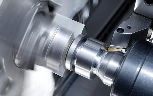
A raw casting never bolts straight into a kinematic chain. The parting line is proud, the ejector pins leave witness marks, and the as-cast faces are flat to maybe 0.3 mm. Bolt faces, dowel bores, bearing seats, and the mating flange all need cutting.
The first operation is usually a datuming cut on the mounting face. Everything downstream references it, so a five-axis setup that machines faces and bores in one fixturing is worth the extra hour. We hold ±0.005 mm on critical bores and Ra 0.8–1.6 μm on sealing faces when the drawing calls for it.
Porosity is the thing that bites. A gas pocket that opens up under a bolt face turns a good part into scrap. For pressure-tight or high-cycle mounts, specify vacuum-assisted casting or a low-porosity process, and ask for a dye penetrant check on machined faces. Raw material check plus in-process monitoring catches most of it before final inspection.
Residual stress is the slower problem. Uneven cooling leaves the casting in a locked state. Machine it today and the faces can move 10 to 20 μm overnight. A stress-relief cycle between roughing and finishing removes most of that drift for mounts with tight parallelism.
- 1Datum firstCut the mounting face before anything else.
- 2One setup for boresKeeps bore-to-face perpendicularity honest.
- 3Stress relief between cutsStops overnight distortion on tight parts.
Alloy choices and their damping trade-offs
Aluminum is the default for moving robot parts because it is light. ADC12 die castings machine cleanly and take anodizing, but their damping is low. If the mount is the only isolation element in the chain, aluminum alone will not do much below 200 Hz.
Ductile iron gives you roughly three to five times the material damping of aluminum and a much higher elastic modulus, which pushes resonance up. The cost is mass. On a fixed base or a floor-mounted pedestal, that trade is usually worth taking.
Zinc alloys sit in between. They cast with excellent detail, hold thin walls, and damp better than aluminum. They are heavier and more expensive per kilogram, so they suit small mounts with fine features rather than large structural brackets.
Stainless and carbon steel are rarely cast for this job. Where corrosion resistance matters, we machine the mount from 316L or 17-4PH bar instead and add a separate elastomer element. That is a legitimate design, just a different one.
- 1ADC12 aluminumLight, easy to cast, low damping on its own.
- 2Ductile ironHigh stiffness and damping, heavy.
- 3Zinc alloyFine detail and thin walls, higher cost.
How the mount interfaces with the frame and actuator
Damping only works if the load path is continuous. A mount bolted to a painted frame face with a soft washer under the head is a spring in series, and it will move. Specify flat, bare metal contact under every bolt head and use hardened washers if the casting face is soft.
Bolt preload matters more than most designers expect. A joint that slips under reversing load frets, and fretting eats the bore. Size the bolts so the friction grip carries the shear, not the dowel pins alone. Dowels then locate; bolts clamp.
If the mount carries a gearbox or a harmonic drive, the pilot bore and the bolt circle set the alignment. Concentricity of 0.02 mm between them is usually enough to keep gear mesh quiet. Tighter than that buys little and costs setup time.
For mobile platforms, add a secondary retention feature. A snubber that only touches after 1 to 2 mm of deflection keeps the elastomer from being torn in a hard stop, and it keeps the arm from walking off its zero position.
- 1Bare metal under bolt headsNo soft coatings in the clamped stack.
- 2Preload over dowelsFriction carries shear; pins locate.
- 3Snubber at 1–2 mm travelProtects the elastomer in a hard stop.
Which route fits which mount
Match the process to quantity, geometry, and damping target.
| Route | Best for | Typical wall | Watch out for |
|---|---|---|---|
| Die cast aluminum + CNC | Runs above a few hundred parts | 2.5–3 mm | Gas porosity under bolt faces |
| Sand cast ductile iron + CNC | Heavy bases, high damping | 5 mm and up | Machining allowance on all faces |
| Zinc die casting + CNC | Small mounts, fine features | 1.5–2.5 mm | Higher cost per kilogram |
| Machined bar + elastomer | Low volume, corrosion resistance | Set by design | Material cost, long cycle time |
| Cast body + bonded insert | Wideband isolation needed | 2.5–3 mm | Bond line quality and cure control |
Pick the process from the damping target, not the price list
If the mount must kill vibration below 200 Hz, cast a ribbed body and bond an elastomer insert. If it only needs stiffness and alignment, cast aluminum plus five-axis finishing is the cheaper, faster route. Choose ductile iron when mass is not a penalty and you want damping from the metal itself.
Damping mount questions engineers ask
How much damping does the casting itself provide?
Material damping in cast aluminum is low, usually under 1 percent of critical. Ductile iron is higher, in the region of 2 to 4 percent depending on graphite shape and section size.
Those numbers matter for ring-down time, not for isolating a 50 Hz disturbance. If you need real isolation, the loss has to come from an elastomer or a tuned element, not from the alloy.
Can you machine a cast mount to ±0.005 mm?
Yes, on the critical features. Datum faces, dowel bores, bearing seats, and pilot diameters are all achievable at ±0.005 mm with the right fixturing and a stable casting.
The as-cast surfaces stay as-cast. It is not economical or useful to machine every face to that tolerance, and doing so only adds cost.
What porosity level is acceptable?
It depends on the function. A mount that only carries static load tolerates scattered porosity away from bolt faces and bores. A pressure-tight or high-cycle mount does not.
For critical parts, specify vacuum-assisted casting and ask for a dye penetrant check on all machined faces. We inspect 100 percent of parts before shipment and can supply reports on request.
Do we need heat treatment between roughing and finishing?
For mounts with tight parallelism across a long span, yes. A stress-relief cycle after rough machining releases the locked-in cooling stress and stops the part from moving during finishing.
For small, stiff mounts with generous tolerances, it is often skipped. The decision should come from the drawing tolerance, not from habit.
What is the minimum order quantity for a cast and machined mount?
There is no minimum order quantity. We run from a single prototype to 10,000+ part runs.
For one-off parts, machining from bar or a printed prototype is usually faster than cutting a die. Casting pays off once the geometry is complex and the quantity is above a few hundred.
Can you supply the elastomer insert as well?
We machine the cast body and can finish the bond face to the flatness and surface texture the insert supplier needs. Bonding and cure are normally handled by the elastomer specialist.
If you want a single source, tell us the insert specification and we will quote the machining scope around it.
Send the drawing and get a DFM review back
Upload your mount drawing and we will return a quotation plus free DFM analysis within 12 hours. Production can start within 24 hours, and parts ship in 3–5 days.
12-hour quote100% inspectionNDA on request
More from the shop floor
We publish setup notes, tooling trials and inspection data from the factory floor.











