
Rapid Tooling Fabrication Process Steps
Six steps from a 3D model to a working mold, die, jig or fixture. This page is written for engineers and buyers who need to plan the sequence, pick parameters, and know where a rapid tooling job usually goes wrong.
In this article
- 1
- 2
- 3
- 4
- 5
- 6
- 7
- 8
- 9
Key takeaways
What Rapid Tooling Actually Means in a Machine Shop
Rapid tooling is the fast route to a mold, die, jig, fixture or gauge that can produce real parts. It is not a different machining process. It is a different set of priorities: get a functional tool into the press or onto the line in days, accept a shorter tool life, and plan to replace it once the design freezes.
In practice that means aluminum cavities, modular inserts, and standard mold bases instead of fully custom steel blocks. A bridge tool that runs 5,000 shots is often enough to validate a design, run a pilot build, and start clinical or road testing. The tool pays for itself through earlier feedback, not through cycle life.
The rapid tooling fabrication process steps below follow the order we use at GreatLight. They apply to injection mold inserts, die-casting dies, stamping dies, weld fixtures, checking fixtures and assembly jigs. The tolerances differ; the sequence does not.
One caution. Rapid tooling is the wrong choice when the geometry is a tall thin rib, a 0.4 mm wall, or a part that needs a hardened tool from day one. Those jobs go straight to conventional tooling, and pushing them into a bridge tool only moves the cost later.
DFM and CAD Preparation Before Any Chip Is Cut
Every job starts with a DFM review of the customer's 3D model. We look for thin walls under 1 mm, internal corners with no tool radius, deep cavities beyond 4× diameter, and tolerances tighter than the process can hold. Most of these are fixable on screen in an afternoon.
Draft matters more than most engineers expect. For a molded part, 1–2° of draft on vertical faces lets the part release without dragging. Zero draft means the molder pulls the part with a pry bar and scratches the cavity. Add draft before the cavity is cut, not after.
Define the parting line and the gate location at this stage. A gate on a cosmetic face leaves a witness mark that no amount of polishing removes. Move it to a hidden edge, and note the chosen location on the tool drawing so the molder and the toolmaker work from the same sheet.
Finally, settle the datum scheme. Pick three datums that a CNC operator can actually reach, then use the same scheme for the tool, the first article and the production part. Mixed datums are the most common cause of a tool that measures well in the shop and fails at the customer's incoming inspection.
Material Selection for Molds, Dies and Fixtures
Material choice sets tool life, cycle time and cost. Aluminum 6061-T6 and 7075 are the default for bridge tools. They machine 3–4× faster than tool steel, take a good polish, and handle short runs well. 7075 holds a better edge on sharp cores but costs more and is harder to weld if you need a repair.
When the tool must survive a full production run, we move to 4140, 4340 or 17-4PH stainless. Pre-hardened 4140 at 28–32 HRC is a common middle ground: machinable with carbide, stable in the press, and heat-treatable later if the program grows.
Fixtures and jigs are a different problem. They need stiffness and wear resistance, not thermal conductivity. Mild steel 1018 or 1045 with black oxide works for most weld and assembly fixtures. Add hardened dowel pins and replaceable wear plates at the contact points.
Do not overlook the resin or the workpiece. A glass-filled nylon at 300 °C will erode an aluminum gate in a few thousand shots. In that case, insert a hardened steel gate block into the aluminum cavity and keep the rest of the tool light and fast.
Why CNC Machining Is the Core of Rapid Tooling Fabrication
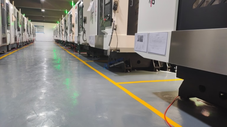
CNC machining is the backbone of rapid tooling fabrication. Molds, dies and fixtures are cut from solid stock, and the machine choice depends on how many faces the part has. A plate with pockets on one side runs on a 3-axis mill. A cavity block with angled water lines or a deep core needs more axes.
For most tooling plates we use 3-axis machines with a 750 × 1,150 × 550 mm travel, which covers a standard mold base. A Ø400 mm rotary table handles round inserts and circular cams in one setup. When the geometry turns on multiple faces, a 5-axis center removes 3–4 setups and the positional error that comes with them.
Roughing and finishing run as separate operations. Rough with a 12–16 mm carbide end mill at 0.5–1.0 mm radial engagement to clear the bulk. Then finish with a 6 mm or 3 mm ball nose at 0.05–0.1 mm stepover. Tool runout above 0.01 mm shows up as a visible band on the cavity wall.
Water lines and ejector holes go in before the final finish pass, not after. Drilling after polishing drags chips across a finished surface. If a water line must be drilled deep, cross-drill from both ends and check the break-through with a borescope.
Post-Processing, Fitting and Finishing the Tool
After machining, edges get a 0.3–0.5 mm break to remove burrs. Sharp cavity edges chip during handling and leave marks on the part. For a molded cavity, we polish to Ra 0.2–0.8 μm on the cosmetic surfaces and leave Ra 1.6–3.2 μm where texture or grip is wanted.
Heat treatment comes next when the material calls for it. 4140 is typically austenitized, quenched and tempered to 28–32 HRC, then ground or EDM-finished because hardening moves the geometry. Aluminum tools skip this step, which is a large part of the time saving.
Hardware fitting is where a tool becomes a tool. Guide pins, bushings, springs, ejector plates and stops are installed and checked for clearance by hand. A guide pin that binds at 0.02 mm will seize once the tool reaches 80 °C in the press.
Surface treatment is optional but useful. Hardcoat anodizing on aluminum cavities adds wear resistance and helps release. Electroless nickel on steel gates and cores resists erosion from glass-filled resins and keeps the finish consistent across a long run.
Assembly, Validation and Documentation
The tool is assembled and run for a first-article sample. We measure the sample against the drawing on a CMM and record every critical dimension. Molds usually need one or two adjustment cycles: gate trim, ejector tuning, or a small weld-and-recut on a short dimension.
Functional testing follows the dimensional check. For a mold, that means a short run of 50–200 shots to confirm cycle time, release behavior and part weight. For a fixture, it means loading three to five real workpieces and confirming repeatability within the stated tolerance.
Documentation closes the job. We hand over the tool drawing as built, the first-article inspection report, material certificates, and a list of critical dimensions to recheck after any repair. Reports are available on request; 100% inspection is standard before shipment.
Keep the as-built record with the tool. When the second cavity or the next-generation tool is ordered, that file is what keeps the two tools interchangeable instead of merely similar.
Rapid Tooling Fabrication Process Steps in Order
Each step lists what to do and the parameter range that keeps the job on schedule.
- 11. DFM and model freezeReview draft (1–2°), wall thickness (≥1 mm), corner radii and tolerances. Return the marked-up model plus a DFM report within 12 hours. Freeze the revision before cutting anything.
- 22. Choose material and tool architectureAluminum 6061-T6 or 7075 for bridge tools, 4140 at 28–32 HRC for longer runs. Decide insert versus solid block, and standard base versus custom.
- 33. Plan the setups and datumsMap every face to a machine. Aim for 2–3 setups on a 5-axis center, or 4–6 on 3-axis. Set datums that stay reachable after heat treat.
- 44. Rough and finish machineRough at 0.5–1.0 mm radial engagement; finish with a 3–6 mm ball nose at 0.05–0.1 mm stepover. Hold ±0.005 mm on mating surfaces.
- 55. Drill water lines and ejector holesCross-drill deep lines from both ends and verify break-through. Keep hole-to-cavity wall thickness above 8 mm on aluminum.
- 66. Post-process and heat treatBreak edges 0.3–0.5 mm, polish cosmetic faces to Ra 0.2–0.8 μm. Heat treat before final grinding or EDM, never after fitting.
- 77. Fit hardware and assembleInstall guide pins, bushings, springs and ejector plates. Check every sliding fit by hand at room temperature and again after a warm-up run.
- 88. First article, test run, documentCMM the first sample, run 50–200 shots or 3–5 workpieces, then issue the as-built drawing and inspection report.
Machine and Material Choices for Rapid Tooling
Pick the row that matches the tool life and geometry you actually need.
| Requirement | Tool material | Machine setup | Typical use |
|---|---|---|---|
| Fewer than 5,000 shots | Aluminum 6061-T6 | 3-axis, 2 setups | Pilot mold, bridge tool |
| Sharp cores, short run | Aluminum 7075 | 3-axis + rotary table | Inserts, small cavities |
| 10,000–50,000 shots | 4140 pre-hard 28–32 HRC | 3-axis + 5-axis | Production-intent mold |
| Corrosive or filled resin | 17-4PH insert in Al block | 5-axis, 3 setups | Glass-filled nylon tools |
| Weld or assembly fixture | 1018 / 1045 steel | 3-axis, 2 setups | Jigs, checking fixtures |
| Angled cores, deep cavities | 4140 or 7075 | 5-axis, 1–2 setups | Complex cavity blocks |
| Large plates over 1 m | 6061-T6 | 3-axis, 750 × 1,150 mm | Mold bases, backing plates |
| Round inserts and cams | 7075 or 4140 | 3-axis + Ø400 mm table | Circular cores, cams |
Plan the tool around the first 5,000 parts
Most rapid tooling programs only need to survive the pilot build. Choose aluminum, skip heat treat, and spend the saved days on validation instead of tool life you may never use.
Rapid Tooling Fabrication Questions
How long does rapid tooling fabrication take?
Quotation and free DFM analysis come back within 12 hours. Production can start within 24 hours of approval, and machined parts ship in 3–5 days. Total tool lead time depends on the number of plates, the heat-treat step and whether a test run is required.
Heat-treated steel tools add the furnace cycle. Aluminum bridge tools skip it, which is why they are the faster option.
What tolerance can you hold on a mold cavity?
We hold ±0.005 mm on critical mating surfaces and shut-offs. Cavity walls and non-critical pockets usually run looser, because tightening them adds cost without improving the part.
Tell us which dimensions control fit and function. Those get the tight tolerance; the rest get a sensible one.
Can you machine a tool from our existing mold base?
Yes. We regularly cut new cavities and cores into a customer-supplied base. Send the base drawing with the actual measured pocket sizes, since used bases rarely match the original print.
We check the guide pin bores and the plate flatness before quoting, because a worn base will transfer its error into the new cavity.
Which materials do you machine for tooling?
Aluminum 6061, 6061-T6, 2024, 7075 and ADC12; stainless 303, 304, 316, 17-4PH and 420; steel 1018, 1045, 4130, 4140, 4340 and tool steel. Copper alloys include C110 and beryllium copper for thermal pins.
We also machine PEEK, POM and phenolic inserts for low-volume tools.
Do you sign an NDA for tooling projects?
Yes. Uploads are secure and confidential, and an NDA is available on request before you send any model. You can also send a simplified model for the first DFM pass.
Tool drawings and inspection reports stay with your project file and are not shared.
What is the minimum order quantity?
There is no minimum order quantity. We run from one prototype tool to 10,000+ part runs. A single cavity block for a pilot mold is a normal order.
For larger programs we can quote the bridge tool and the production tool together so you can compare the total cost.
Send Your Tooling Model for a DFM Review
Upload a 3D model and get a quotation with free DFM analysis within 12 hours. No minimum order quantity.
12-hour quote±0.005 mm100% inspectionNDA on request
More from GreatLight
We publish setup notes, tooling trials and inspection data from the factory floor.











