Aiming at the problem that forming tools for thread turning are expensive and it is difficult to guarantee the processing quality by manual grinding, CAXA CNC lathes are used for special thread programming, which can reduce the production costs while guaranteeing quality.
PART 1Preface
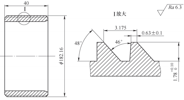
Thread turning plays an important role in mechanical processing. Thread turning with forming tool can ensure processing accuracy and improve production efficiency. However, forming tools with special threads are expensive or even unavailable. If grinding is done by hand, it is difficult to guarantee quality. By using CAXA CNC machines for programming special threads, production costs can be reduced while ensuring quality.[1]. This article takes the saw-shaped thread commonly used in petroleum equipment as an example (see Figure 1) and uses CAXA CAM 2022 (X64) CNC lathe software for programming.
Figure 1 Thread pattern
The thread is a single thread with a pitch of 3.175 mm, a thread height of 1.78 mm, a profile angle of 46°, a conductive flank angle of 48°, a load flank angle of 4°, right-hand thread, main thread diameter of 182.16mm and workpiece material of 42CrMo, hardness 285~320HBW. The bottom of the thread can have an arc, with a maximum of R0.25mm. The thread turning tool uses a cutting tool with an included angle of 30° and a tool tip arc radius of 0.2mm for turning. The lathe is a horizontal lathe of the FANUC 0i-TF series system. Use a projector for thread inspection, use non-stick paste and inspect on the projector. For ease of inspection, 50x magnified images and mold release sections can be drawn for comparison.
Software Settings PART 2
Post-processing settings: open the software, click “CNC Car”, click “Post-Settings” and select “Spindle”. The interface is shown in Figure 2. Click “New Control System” and “New Device Configuration” in the lower left corner, and then click “Save”. The settings are respectively: spindle forward M03, spindle stop M05, coolant on M08, coolant off M09, program stop M30. Select “Turn”, the interface is as shown in Figure 3, and apply the G32 pitch thread programming command. After completing the settings according to the operating system, click OK.

Figure 2 Post-set spindle limit

Figure 3 Post-adjustment turning interface
PART 3Create Processing Drawings
Before using CAXA CNC lathe programming, you must first create a 1:1 two-dimensional pattern in CAXA CNC lathe software. The center axis of the part coincides with the software X axis and the right end surface coincides with the software X axis. Software Y axis. That is, the two-dimensional pattern and coordinate system of the CNC lathe workpiece. Consistent, the zero point of the part is defined at the center of the right end face. Draw a complete thread profile of approximately 6mm on the right side of the part, ensuring that the major and minor diameters of the thread profile are on the same horizontal line as the part and that the dimensions are consistent as shown in Figure 4. The principle of selecting the position of the first thread profile: ensure that the feed and the workpiece cannot collide and minimize the distance of the idle tool. In daily programming, the position of the first thread should be drawn according to the step size and tool conditions. .

Figure 4 CAXA model and complete tooth type
Draw a grid on the thread profile (see Figure 5) and offset it by 0.3mm according to the profile of the thread profile. This time, the arc radius of the tool tip is selected as 0.2mm, the center of the tool tip circle is the center point of the tool, and a margin of 0.1 mm is left on one side for finishing. The grid spacing is set to 0.2 mm, and the tooth profile is divided into 9 layers in the diameter direction. The black dot of the grid intersection in Figure 5 is used as a starting point for the next programming step.

Figure 5 Tooth type gear
PART 4Create a Toolpath
Click “CNC Turning” in the menu bar, select “Thread Processing” and click “Thread Settings”. The interface is shown in Figure 6. Select “External thread”, with a constant pitch of 3.175mm, a cutting extension of 0mm and a cutting extension of 6mm (in order to avoid the thread not being turned, which would prevent the thread from being screwed into place)[2]. The value setting is adjusted according to the thread pitch size, tool condition and thread end point selection. The thread pitch is set to 0.01 mm and the number of thread heads is 1.

Figure 6 Thread settings configuration interface
Set the processing parameters (see Figure 7): roughing depth is 0.01 mm; set the tool advance and retract mode (see Figure 8): set the rapid retraction distance to 2.5mm, which is generally not less than the tooth height.

Figure 7 Processing configuration interface

Figure 8 Setting interface for tool advance and retract methods
Set the tool parameters (see Figure 9): fill in 1 for the tool number, select “No” for rapid advance and retraction of the tool in the cutting quantity, set the approach speed to 3mm, set the retract speed to 5mm and the tool feed amount defaults to 3.175mm, click “Incoming”.

Figure 9 Tool settings interface
Click “Geometry” in the tab, select point 1 in the upper right corner of the grid in Figure 5 as the starting point of the thread, and select the contact point between the left chamfer and the large diameter of the thread as period. . The selection of the tool feed and retract point should be in the same vertical direction as the thread starting point. In order to facilitate selection, a vertical auxiliary line should be drawn from the starting point of the thread. the value of rapid tool retraction distance in tool feed and retract mode in Figure 8. In this paper, the first adjustment length is 5 mm. If the value is too large, the empty tool path will be too long and will cost you time. . Finally click on “OK” to generate the toolpath.
Copy the tool path: click the generated tool path, all the tool path is selected, right click, translate and copy, take the lower right corner of the tool path diagram as the base point and copy the tool path into the tooth type mesh in Figure 5 in order. In black point, the copy order is right to left, once the first layer is copied, the second layer is also copied from right to left, and so on. To copy the tool path, you can also use the “Common” → “Toolbar Array” command on the title bar. It should be pointed out that the toolpath of the final generated program is related to the order of copying toolpaths, so copying toolpaths must be carried out in a certain order, otherwise safety accidents such that a stab wound or knife collision may occur. .
Post-processing generation program PART 5
After generating the tool path, click the Generate Zip Code icon in the menu bar, select the required tower system and storage location, click OK after the settings are completed, select the path of the tool and the program can be generated.[3]The interface is shown in Figure 10. Use CIMCO edit 8.02.16 software to simulate the generated program. After confirming that the tool path is correct, import the program into the CNC lathe.

Figure 10 Post-processing program generation interface
Program modification: Tool speeds S1000, M03, M08, M09 and M01 appear repeatedly in post-processing and it is recommended to remove them. The rotation speed and quick positioning point are added to the program start position to ensure a safe position for the tool, and a safe position for turning tool changes is added at the end of the program. Feed the program into the CNC machine tool and process the finished product (see Figure 11). In order to facilitate observation, the left side surface has been phosphated, and the finished product after machining is on the right side. Use non-stick paste to project the tooth profile onto a 50x projector (see Figure 12). After testing, the size and angle of the tooth profile can meet the design requirements, as well as the conduction flank surfaces of the thread and load bearing. the sides are smooth, without obvious traces of connection to the knife.

Figure 11 Finished processed product

Figure 12 Tooth profile
PART 6Conclusion
CAXA special thread CNC turning solves the problem of unavailable forming tools, reduces the difficulty of thread programming to a certain extent, and also guarantees the production quality, which is conducive to improving the efficiency of the production, reduction of production costs and convenience of enterprise production. The specific summary is as follows.
1) This method is very versatile, suitable for various special-shaped threads, and solves the problem of tool customization for small batch thread production.
2) This program uses the tip of the tool to turn. When installing the tool, make sure that the sharp edges on both sides of the tool do not interfere with the workpiece.
3) When dividing the thread profile mesh, considering the size of the thread profile, it is often not possible to achieve a division equal to 100%. However, the actual mesh can be divided according to the actual conditions of machine tools, tools, products, etc.
4) The toolpath of the final generated program is related to the order of copying toolpaths, so copying toolpaths must be done in a certain order, otherwise safety accidents such as a stab wound or knife collision may occur.
5) When adjusting the cutting tool, the turning tool in the diameter direction lightly touches the outer circle of the workpiece to complete the tool adjustment. Since the center of the tool arc is used as the central programming point, wear must be added to the tip tool compensation. The external thread is a negative value, specifically twice the arc radius of the tool tip. , the tool compensation is -0.4 mm.
6) In this case, a finishing allowance of 0.1 mm is reserved and finishing treatment is required. Only both sides of the thread and the bottom of the thread are processed. The step distance of the finishing tool path is smaller and needs to be adjusted. according to the actual situation.
7) This method also has disadvantages, such as long processing time and lower precision than the forming knife. If necessary, the forming knife can be used for finishing.
Daguang focuses on providing solutions such as precision CNC machining services (3-axis, 4-axis, 5-axis machining), CNC milling, 3D printing and rapid prototyping services.


