01
Preface
Thin tube parts have a small diameter, thin wall thickness, and relatively large aspect ratio and aperture ratio. Due to the long overhang and poor rigidity, vibration is likely to occur during processing, which causes deformation and loosening of the pipe parts, resulting in tool damage or lifespan. reduced life. In addition, the processing efficiency is low, the surface quality is poor, and the product. quality is difficult to guarantee and parts may even be scrapped and many other problems.
02
Parts Analysis
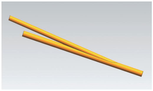
The welded frame parts shown in Figure 1 are processed in large batches. They come in the form of a thin rod, with a minimum processing angle of 3°, diameter of 40 mm, wall thickness of 3 mm, aspect ratio of 25. poor rigidity and prone to vibration during treatment. Causes tool damage and how to tighten and process becomes a problem. If processed and clamped by the conventional method, the machining surface of the workpiece will exceed the clamping range, causing vibration during processing, and the sharp corners of the inclined arc surface will be torn off, damaging the tool and reducing treatment. efficiency, and even cause the part and operation to be scrapped. In the event of accidents such as personal injury, reasonable tightening methods should be developed to solve these problems.
a) Connection diagram of pipe fittings

b) Structure of the arc surface and dimensions of the parts
Figure 1 Frame assembly and welded parts
03
Original treatment method
The original processing method and clamping are shown in Figure 2. Use a pressure plate to maintain the unprocessed position of the workpiece, with the inclined part coming out of the workbench, and use the tool to mill in layers. The room is seriously vibrating. The cutting depth of each layer is 0.2 mm. the final cutting depth is 0.05mm. The processing efficiency is low and the workpiece surface is poor.[1]。

a) Tightening instructions

b) Actual processing and tightening
Figure 2 Processing method and original tightening
04
Improved tooling
Make the following improvements to the tools.
1) Reasonably design the tooling so that the tooling and parts are integrated. The improved tooling is shown in Figure 3. In the first processing, the parts and tooling are processed together, and the excess parts of the tooling are removed to avoid collision between the tool and tooling during the normal processing, and the tooling and the workpiece are in contact with the maximum area to achieve the packaging purpose and make the workpiece more precise.

Figure 3 Improved tooling
2) After the tooling is processed and formed, the processing program is optimized and only the parts are processed as the interference surface, and the appropriate tools and cutting parameters are selected to make the processing process smooth and avoid adjustments . achieve better rigidity during the processing process of pressing plates, moving horns and other tedious tasks.
3) As shown in Figure 4, the tooling cover is made of aluminum to reduce mass and reduce labor intensity. The middle is made into an arc shape, which can fit the parts closely and improve the processing stability.[2]. The treatment effect is shown in Figure 5.

Figure 4 Tooling cover

Figure 5 Treatment effect
05
Tool Improvements
(1) Because the workpiece overhang is too long, the original tool selected is a φ32mm insert milling cutter with a smaller diameter and a sharp cutting edge. The cutting angle of the tool is approximately 5°, the edge inclination angle is 3°. and the main deviation angle is 90°. Choosing a smaller cutting depth and using segmented cutting methods can effectively protect the tool, but the tool tip is relatively thin and is still prone to chipping during processing.
(2) The tool currently used is a φ32mm high-speed milling cutter. The cutting angle of the tool is 1° to 2°, the edge inclination angle is 0°, the main deviation angle is about 120°, and the clearance angle is 30.°. During processing, downward cutting force is generated, the cutting speed is fast, and can effectively prevent vibration. The blade is thick and has good vibration resistance.[3]。
The comparison of machining tools is shown in Figure 6.

a) Right angle milling cutter b) High speed milling cutter
Figure 6 Comparison of machining tools
06
Improvements to processing methods
Adopt the segmented processing strategy (see Figure 7), start processing from the end with the least rigidity of the workpiece, divide the processing into three sections, and gradually finish processing to the left, with a cutting depth of 1mm every time.[4]。

a) First processing stage b) Second processing stage

c) Third stage machining d) Contour finishing
Figure 7 Segmented processing
07
Analysis of treatment effect
Comparison of process and treatment effects before and after improvement is shown in Table 1.
As shown in Table 1, by using tooling and selecting a high-speed milling cutter with a bevel for rough machining, the cutting force becomes a pressing force, which does not cause the workpiece to vibrate, and the corners are sharp of the piece are well preserved. Fully meets technical requirements. The surface quality of parts has been significantly improved, the processing efficiency has been increased by more than 6 times, and the processing cost of each tool has been saved by more than 200 yuan.
Table 1 Comparison of process and treatment effects before and after improvement

08
Innovation points and technical summary
1) Improve processing tools and methods. Intelligently designed special tools. During processing, the tooling and parts are closely fitted and integrated, that is, the tooling is also set as a processing part and processed with the parts. After processing, the parts can be wrapped better, the rigidity of the parts is improved. and the soreness is basically eliminated. The chatter phenomenon in pipe processing.
2) Optimize the processing program and set the tooling as the interference surface so that the processing of the oblique arc surface of the workpiece can be carried out at one time, avoiding tedious auxiliary work such as adjusting the pressure plate and the movement of the pads.
3) Optimize cutting tools and processing parameters, improve processing methods, increase processing efficiency by more than 6 times, and reduce production costs.
09
Conclusion
This paper presents a method for machining thin tubes with large angles and inclined arc surfaces. It performs process analysis on part vibration and tool damage during processing, through tooling improvement, parameter optimization and tool setup re-optimization, during the treatment. and parts Interference fit and integration eliminate the chatter phenomenon in the processing of long and thin tubes and long inclined arc surfaces, improve processing efficiency, and greatly improve tool life. It has obtained good economic benefits and has been used in similar products of the company. . Promote applications.
Daguang focuses on providing solutions such as precision CNC machining services (3-axis, 4-axis, 5-axis machining), CNC milling, 3D printing and rapid prototyping services.


