
Metal 3D Printing DMLS Aluminum Parts
This page explains how laser powder-bed fusion builds aluminum parts, what the as-built material can and cannot do, and where CNC finishing enters the chain. It is written for design and manufacturing engineers who need to decide whether DMLS aluminum parts fit their application before committing to a build.
How DMLS Aluminum Parts Are Built
DMLS aluminum parts are built in a powder bed. A recoater spreads a layer of gas-atomized aluminum powder, usually 20–60 μm thick, across a build plate inside an inert argon atmosphere. A fiber laser then scans the cross-section of the part, melting the powder into a solid track. The plate drops by one layer thickness, fresh powder is spread, and the cycle repeats until the part is complete.
The laser spot is small, around 70–100 μm, and the melt pool it creates is only a few hundred microns wide. That pool solidifies in milliseconds. Cooling rates reach 10⁵ to 10⁶ K/s, which is orders of magnitude faster than casting. This fast quench is the reason the material behaves differently from wrought aluminum, and it shapes everything downstream.
Scan strategy matters as much as laser power. Islands, stripes, and rotation between layers spread the heat input so the part does not build up stress in one direction. A well-tuned recipe uses hatch spacing around 0.10–0.14 mm and layer thickness of 30–50 μm for aluminum. Get these settings wrong and the part will still look correct when it comes off the plate, then warp after support removal.
For DMLS aluminum parts, build orientation decides more than most engineers expect. Overhangs below roughly 45° need support. Down-facing surfaces pick up roughness from the powder that is partially melted beneath them. Holes built horizontally come out oval rather than round. All of this gets corrected later, either in the slicing software or on a CNC.
- 1Layer thickness30–50 μm for aluminum; thinner layers cost more time per part
- 2Melt poolfew hundred microns wide, solidifying in milliseconds
- 3Inert gasargon keeps oxygen low; aluminum oxidizes fast when hot
- 4Scan rotation67° rotation between layers is common to reduce directional stress
Which Aluminum Alloys Fit Powder-Bed Fusion
AlSi10Mg is the workhorse. Its silicon content gives it a narrow freezing range, which means the melt pool solidifies cleanly instead of cracking. Tensile strength in the as-built condition sits around 350–400 MPa, and a T6-style heat treatment can push yield strength higher while improving ductility. For most DMLS aluminum parts, this is the alloy to start with.
AlSi7Mg and AlSi12 are close relatives. AlSi12 flows a little better and is often chosen for thin walls. AlSi7Mg trades some castability for slightly better mechanical properties after heat treatment. The differences are modest, and the choice usually comes down to what the supplier has qualified rather than a big performance gap.
High-strength 7075 and 6061 do not print cleanly. Both have wide freezing ranges and are prone to hot cracking during solidification. Research has produced printable versions with grain refiners, but they are not standard production alloys. If your design calls for 7075 properties, the practical route is to print in AlSi10Mg for geometry and accept the material change, or machine the part from 7075 bar instead.
Copper and aluminum composites exist, but they are specialty powders with limited availability. The engineering trade is rarely worth it. For thermal work, AlSi10Mg with a machined interface often performs well enough, and 6061 or 2024 bar stock can handle the conductive paths where DMLS geometry adds no value.
Residual Stress and Distortion in DMLS Aluminum Parts
Residual stress is the central problem in aluminum powder-bed fusion. Each laser pass deposits heat into a thin layer sitting on cold material below. The top expands, the layer beneath resists, and stress locks in as the melt cools. Aluminum conducts heat roughly five times faster than titanium, so the gradient is steeper and the stress builds faster.
The first symptom is curl. Thin walls, long unsupported spans, and sharp corners lift from the plate. The second symptom appears after the build, when supports are cut and the part springs. A bracket that measured within tolerance on the plate can move 0.2–0.5 mm once it is free. Delicate lattice structures sometimes twist in ways that are hard to predict.
Three controls reduce the risk. Preheat the build plate to 150–200 °C so the substrate is not cold. Use a scan strategy that rotates direction between layers. Design supports that anchor the part to the plate and carry heat away from overhangs. These are process decisions made before the first layer, not fixes applied afterward.
Stress relief comes next. A heat treatment at 300 °C for two hours in an inert atmosphere relaxes much of the locked-in stress. For parts that need maximum properties, a solution treatment and artificial aging cycle follows. The exact schedule depends on the alloy and the required ductility, so it should be agreed with the heat treater before the build starts.
What As-Built DMLS Aluminum Parts Cannot Hold
As-built surfaces are rough. Up-facing surfaces typically land around Ra 8–12 μm, and down-facing surfaces are worse because they sit on partially melted powder. That roughness affects fatigue life and sealing. Any surface that slides, seals, or carries cyclic load needs machining, and the design should leave stock for it.
Tolerances in the as-built state are loose compared with machining. General dimensions might hold ±0.1 mm on a good day, but thin features, long spans, and anything affected by thermal distortion will drift further. Calling out ±0.005 mm on a print drawing is not realistic. The usual approach is to print near net shape and machine the critical interfaces.
Holes are a specific case. A hole built in the vertical direction comes out reasonably round. A hole built horizontally sags at the top and measures oval. Threads printed directly are weak and imprecise. Drill and tap after the build, or design the hole undersize and ream it. For DMLS aluminum parts with many threaded holes, it is often faster to print the blank and let a CNC do all the hole work.
Internal channels are where DMLS earns its place. Conformal cooling paths, lattice cores, and organic manifolds cannot be machined. They can be printed. The trade is that the channel walls are rough, which raises pressure drop, and internal support removal is difficult to verify. Design channels with generous radii and avoid long horizontal runs.
Why DMLS Aluminum Parts Usually End on a CNC
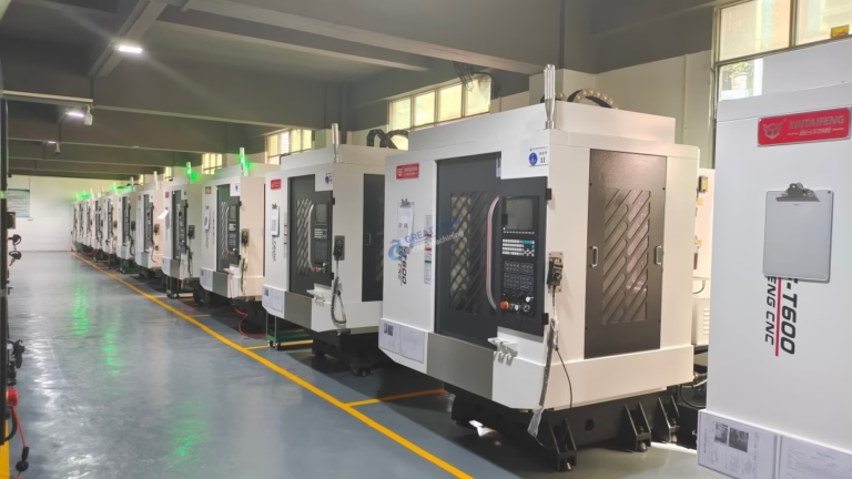
A printed part is a near-net shape, not a finished component. Support removal, stress relief, and machining follow the build. At GreatLight, the CNC side of that chain is where the part becomes a usable component. We run 16 simultaneous 5-axis machining centers, 12 four-axis mills, 27 three-axis machines, and 16 mill-turn centers, with a maximum processing size of 4,000 mm.
The machining step handles the interfaces that DMLS cannot hold. Datum faces get skimmed. Bores get reamed or bored to ±0.005 mm. Sealing surfaces are milled to Ra 0.8–1.6 μm. Threads are cut. If a printed boss needs to mate with a cast housing, this is the operation that makes it fit, and it is planned before the build so there is enough stock to remove.
Fixturing printed parts takes thought. The geometry is often organic and the wall sections are thin, so clamping pressure can deform the part before the cutter touches it. Soft jaws, custom nests, and low-pressure vises are common. For delicate lattices, we sometimes leave a printed base that the vise can grip, then cut it off in a second operation.
Materials come off the same floor. We machine 6061, 6061-T6, 2024, 5052, 5083, 6063, 6082, 7075, and ADC12, along with stainless, steel, titanium, and copper alloys. That range matters when a design mixes printed aluminum with machined stainless inserts, because the tolerances and finishes can be held under one roof.
When DMLS Aluminum Beats Machining
Use this table to decide which route fits the part in front of you.
| Part characteristic | DMLS aluminum | CNC from bar |
|---|---|---|
| Internal conformal channels | Can be built | Not possible |
| Lattice or organic core | Printed in one piece | Multiple bonded pieces |
| Simple prismatic shape | Slower and costlier | Fast and cheaper |
| Tight bore tolerance ±0.005 mm | Needs post-machining | Held directly |
| Wall thickness below 1 mm | Feasible with care | Deflection risk in thin walls |
| Part count of 1–50 | No tooling needed | No tooling needed |
| Part count above 1,000 | Cost per part stays high | Cost per part drops |
| Threaded holes | Drill and tap after build | Cut in one setup |
The Short Version
If the part has internal channels, lattices, or organic geometry that cannot be cut, print it in AlSi10Mg and machine the critical interfaces. If the part is prismatic, needs ±0.005 mm everywhere, or will run in thousands, machine it from bar stock and skip the print.
Questions Engineers Ask
What is the difference between DMLS and SLM for aluminum?
The two terms describe the same physics: a laser melts metal powder layer by layer in an inert atmosphere. DMLS is a trademarked name from one equipment maker, and SLM is used by others. For aluminum, the practical differences come from the machine, the laser spot size, and the qualified recipe, not from the label.
Can DMLS aluminum parts be anodized?
Yes, but the high silicon content changes the result. AlSi10Mg anodizes to a darker, more gray finish than 6061, and hardcoat coverage is less uniform because silicon particles do not oxidize the same way aluminum does. If a specific color match matters, test a coupon before running the batch.
How small can internal channels be?
Channels around 1 mm diameter can be printed, but below that the risk of powder blockage and incomplete support removal rises quickly. A 1.5–2 mm channel with rounded turns and a clear escape path for trapped powder is far more reliable. Design the channel for the cleaning method, not just the print.
Do I need heat treatment after the build?
For most structural parts, yes. A stress relief at 300 °C for two hours reduces distortion risk before machining. Parts that carry load or see fatigue benefit from a full solution and aging cycle. Skipping heat treatment leaves residual stress that can move the part during or after machining.
What lead time should I expect?
At GreatLight, quotation and free DFM analysis come back within 12 hours, and production can start within 24 hours. Parts ship in 3–5 days once the build and finishing operations are complete. The exact schedule depends on build height, heat treatment, and how much machining the part needs.
Is there a minimum order quantity?
No. We run from one prototype to 10,000+ part runs. Powder-bed printing has no tooling cost, so a single part is viable. The cost per part falls only slightly with volume because machine time dominates, unlike casting or injection molding.
Send the STEP File and We Will Check It
Upload your model and we will return a DFM analysis within 12 hours, covering print orientation, support strategy, stock left for machining, and the finishes that fit. Uploads stay confidential, and an NDA is available on request.
12-hour quote and DFM100% inspection before shipmentNo minimum order quantity
More from GreatLight
We publish setup notes, tooling trials and inspection data from the factory floor.











