
Large-Scale 3D Printing: How Big Builds Actually Work
Large-scale 3D printing builds parts from a few hundred millimeters up to several meters, using gantry extrusion, robotic arms, pellet-fed printers, or large powder beds. This guide covers the mechanism behind each route, the physics that limits accuracy, and the point where machining becomes the better choice.
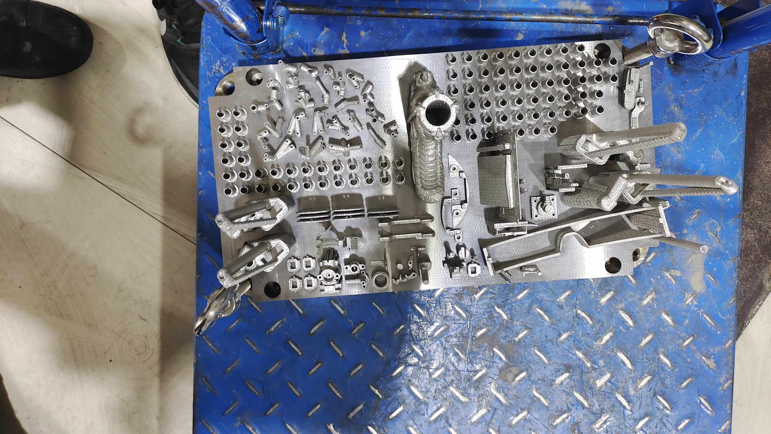
What Counts as Large-Scale 3D Printing
A desktop printer works inside a 250 mm cube. Large-scale 3D printing starts where that envelope ends. In practice, the term covers machines that build parts from roughly 500 mm up to several meters in a single piece. The boundary is not just size. Big printers also change the material feed, the motion system, and the way heat moves through the part.
Three things usually push a part into this category. The part is too big to fit any standard build chamber. The part is big enough that joining smaller printed sections would add cost, weight, or a weak seam. Or the part is a one-off tool, jig, or mold where the lead time of a printed build beats the lead time of a machined one.
Size alone does not make a part a good candidate. A 900 mm bracket with a ±0.05 mm bore is a machining job, not a printing job. Additive gives you geometry freedom and speed at low volume. It does not give you tight tolerances on large surfaces without post-machining.
The machines in this class split into two families. Extrusion systems melt and push material through a nozzle. Powder systems fuse material in a bed. Extrusion scales more cheaply. Powder scales better for fine detail but has a smaller practical ceiling.
- 1ExtrusionFilament, pellet, or concrete pushed through a nozzle on a gantry or robot arm
- 2Powder bedLaser or binder fuses powder layer by layer inside a heated chamber
- 3Practical sizeExtrusion reaches several meters; powder beds typically stay under about 1 m
How Each Large-Scale 3D Printing Route Works
Gantry extrusion is the most common large-scale 3D printing method. A frame carries the print head in X, Y, and Z over a fixed bed. A screw or pellet extruder melts polymer and lays a bead 0.5 mm to 3 mm wide. Layer heights run 0.2 mm to 1.5 mm. The wide bead is what makes the build fast, and it is also what limits surface finish.
Robotic arm extrusion replaces the gantry with a 6-axis arm. This lets the head tilt, so you can print on a curved surface or build a part in a non-planar direction. It is common for concrete and for large composite tooling. The trade-off is programming effort. Every new part needs a toolpath that the arm can reach without collision.
Pellet-fed printers use plastic granules instead of filament. Material cost drops, and you can print with filled compounds such as glass-filled PA or carbon-filled ABS. Feed rate is higher, but melt control is harder. Expect more variation in bead width than a filament machine.
Large powder systems use a laser or a binder to fuse nylon, TPU, or metal powder. The bed is heated to reduce curl. Build volume is limited by how evenly you can hold temperature across the bed, so these machines rarely exceed about 1 m in the longest axis.
- 1Bead width0.5–3 mm on extrusion machines; wider bead means faster build and rougher skin
- 2Layer height0.2–1.5 mm typical; below 0.2 mm slows the build sharply
- 3Nozzle temperatureSet by polymer: ABS around 240–270 °C, PEEK above 380 °C
- 4Chamber heatWarm chamber reduces warp; many large cells run 40–80 °C air temperature
Why Big Prints Warp, Shrink, and Drift
Every extruded bead cools after it leaves the nozzle. As it cools it contracts. On a small part the contraction is a few tenths of a millimeter and the bed holds the part flat. On a 1,200 mm part the same contraction accumulates into millimeters of pull at the corners. That pull lifts the part off the bed or bows the base.
Thermal gradient is the main driver. The top of the part is hot, the bottom is cooler, and the difference grows with build height. A tall print is not one solid object while it is being made; it is a stiffening shell with a hot core. When the gradient is too steep, the part curls at the edges mid-build.
Shrinkage also depends on material and infill. Semi-crystalline polymers such as PA and PP shrink more than amorphous ones such as ABS or PC. Low infill leaves internal voids that let the skin move. A part printed at 15 percent infill can measure differently after cooling than the same part at 50 percent.
There is also machine drift. A gantry that spans 2,000 mm will sag slightly under its own weight and under the weight of the head. Over a long build, small positioning errors add up. This is why large extrusion parts are usually printed oversize and then machined on the critical faces.
- 1WarpCooling contraction pulls corners up; worst on long, flat, thin bases
- 2ShrinkSemi-crystalline polymers shrink more than amorphous ones
- 3Gantry sagLong spans deflect; keep the head light and the frame stiff
- 4CurePost-cure or stress-relief can move a part after it measures fine
Where Large-Scale 3D Printing Stops Being the Right Answer
Additive is strong in the first few hundred parts and weak in the thousands. If you need 10,000 identical brackets, a printed one costs more per part than a machined or molded one. The economics flip around the point where tooling cost is amortized, and that point depends on part size and material.
Tolerances are the second limit. A large extrusion part typically holds ±0.5 mm on an as-printed feature, and worse on long spans. If your drawing calls for ±0.05 mm on a bore, printing alone will not get there. The usual fix is to print oversize and machine the critical features.
Anisotropy is the third. A printed part is weaker between layers than along them. Under load, a printed bracket can split along a layer line. If the part sees tensile load across the build direction, orient the print so the layers run with the load, or switch to a machined or cast part.
Surface finish matters too. As-printed extrusion surfaces sit around Ra 6–12 μm. That is fine for a jig body, poor for a sealing face or a bearing bore. Bead blasting, tumbling, or machining brings it down, but each step adds time and cost.
- 1VolumeAdditive wins at low volume; tooling wins at high volume
- 2ToleranceAs-printed large parts rarely beat ±0.5 mm
- 3Load directionLayer bonds are the weak plane; plan print orientation around the load
- 4FinishAs-printed extrusion is rough; sealing and bearing faces need post-work
Printing Oversize and Finishing on a CNC
The most practical large-part workflow is hybrid: print near net shape, then machine the faces that matter. Printing gets you a blank in days. Machining gets you the tolerance, the finish, and the flat datum the drawing asks for. Neither step alone does both jobs well.
On the machining side, large parts need large travels. A 4,000 × 400 × 150 mm travel envelope covers long rails, beams, and tooling plates. A Ø400 mm rotary table handles round features on the same setup, which keeps runout tight without re-fixturing.
For parts that need both a big envelope and tight tolerance, a 5-axis center with 16 simultaneous axes across the shop lets us reach angled faces in one setup. Fewer setups means less stack-up error. That matters most on a printed blank, because the blank itself already carries some variation.
Watch the setup, not just the cut. A printed blank is not as stiff as a billet, and it can move when you release the clamps. Light passes, sharp tooling, and a stress-relief step before the finish pass keep the part in tolerance.
- 1PrintNear net shape, fast, low tooling cost
- 2MachineCritical faces, bores, and datums to ±0.005 mm
- 3FixturePrinted blanks deflect; support them and take light passes
- 4InspectCheck after clamp release, not only on the machine
Choosing a Build Route by Part and Requirement
Match the route to the part, not to the machine you already have.
| Part or need | Best fit | Why | Watch out for |
|---|---|---|---|
| Large tooling, jigs, fixtures | Gantry extrusion | Cheap material, fast build, easy to reprint | Rough skin, needs machining on locating faces |
| Concrete or architectural form | Robotic arm extrusion | Free-form paths, no mold needed | Programming time, surface finish is coarse |
| Filled or recycled polymer | Pellet-fed extrusion | Low material cost, high feed rate | Harder melt control, wider bead variation |
| Fine detail on a smaller part | Powder bed fusion | Thin layers, complex internal channels | Build volume caps out near 1 m |
| Tight bore or flat face | CNC machining | Holds ±0.005 mm and Ra 0.2–0.8 μm | Slower to first part at very low volume |
| Metal part with internal channels | Metal binder jet or DMLS | Channels that cannot be drilled | Sinter shrink, needs support removal |
Pick the route by the drawing, not by the trend
If the part is large, low volume, and geometrically complex, print it. If the part is large and your drawing has tight bores, flat datums, or a sealing face, print it oversize and machine those features. If the part is large and you need thousands of them, machine or mold it.
Large-Scale 3D Printing Questions Engineers Ask
How accurate is a large printed part?
As-printed extrusion parts usually hold around ±0.5 mm on a well-tuned machine, and the error grows with part length. Long spans, thin bases, and tall builds are the worst cases.
If the drawing needs ±0.05 mm on a bore or a flat face, print oversize and machine that feature. The printed body carries the geometry; the machined feature carries the tolerance.
What is the largest part you can print in one piece?
Gantry and robotic extrusion systems can build parts several meters long. Powder-bed systems are limited by chamber heating, so they typically stay under about 1 m in the longest axis.
Beyond the machine limit, you can print in sections and join them, but the joint becomes a weak point and a leak path. Check whether the joint is acceptable before you design around it.
Can a printed part be machined afterward?
Yes, and for many large parts that is the intended workflow. Print near net shape, then face, bore, and slot the critical features on a CNC.
Print the blank with 1–3 mm of stock on machined faces. Skipping that allowance is the most common mistake we see, because the printed surface rarely cleans up in one pass.
Why do large prints warp even with a heated chamber?
A heated chamber reduces the gradient but does not remove it. The top of a tall part is still hotter than the base, and every cooling bead contracts.
Fixes that help: a brim or raft for bed adhesion, slower cooling, higher chamber temperature, and a design that avoids long thin flanges. Semi-crystalline polymers warp more than amorphous ones.
When should we machine instead of print?
Machine when the drawing is tolerance-driven, when the load crosses layer lines, or when the quantity is high enough that tooling amortizes.
Print when the part is large, low volume, and geometrically complex. The two routes are not competitors on most real jobs; the best result is often one of each.
What materials are used for large-scale printing?
Extrusion covers ABS, PC, PA, PP, PETG, and filled grades such as glass-filled PA or carbon-filled ABS. Pellet machines handle the same families at lower material cost.
Powder systems use nylon, TPU, and metal powders. If the final part must be metal with tight tolerance, printing is usually the blank step and machining is the finishing step.
Send the drawing and get a routing answer
Upload the part and we will tell you whether printing, machining, or a print-then-machine route fits the drawing, with DFM notes and a quote.
Quotation and DFM within 12 hoursProduction can start within 24 hours100% inspection before shipmentNDA on request
More from GreatLight
We publish setup notes, tooling trials and inspection data from the factory floor.











