
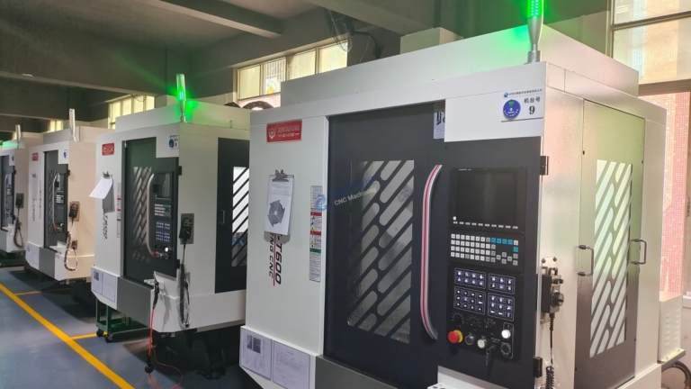
How To Use CNC Wood Carving Machine?
In the world of precision parts machining and customization, the application of CNC technology extends far beyond metals and plastics. For clients in industries ranging from bespoke furniture and architectural millwork to artistic sculpture and musical instrument manufacturing, mastering the use of a CNC wood carving machine is a pivotal skill that bridges digital design with tangible, intricate wooden creations. While our core expertise at GreatLight CNC Machining Factory lies in high-tolerance metal components, the fundamental principles of CNC programming, toolpath strategy, and precision execution are universal. This guide will delve into the professional workflow of operating a CNC wood carving machine, offering insights that parallel the meticulous approach required in precision five-axis CNC machining.
H2: Understanding Your CNC Wood Carving Machine
Before initiating any project, a thorough understanding of your equipment is paramount. Unlike industrial metal-cutting CNCs, wood carving machines are optimized for different forces, speeds, and material characteristics.
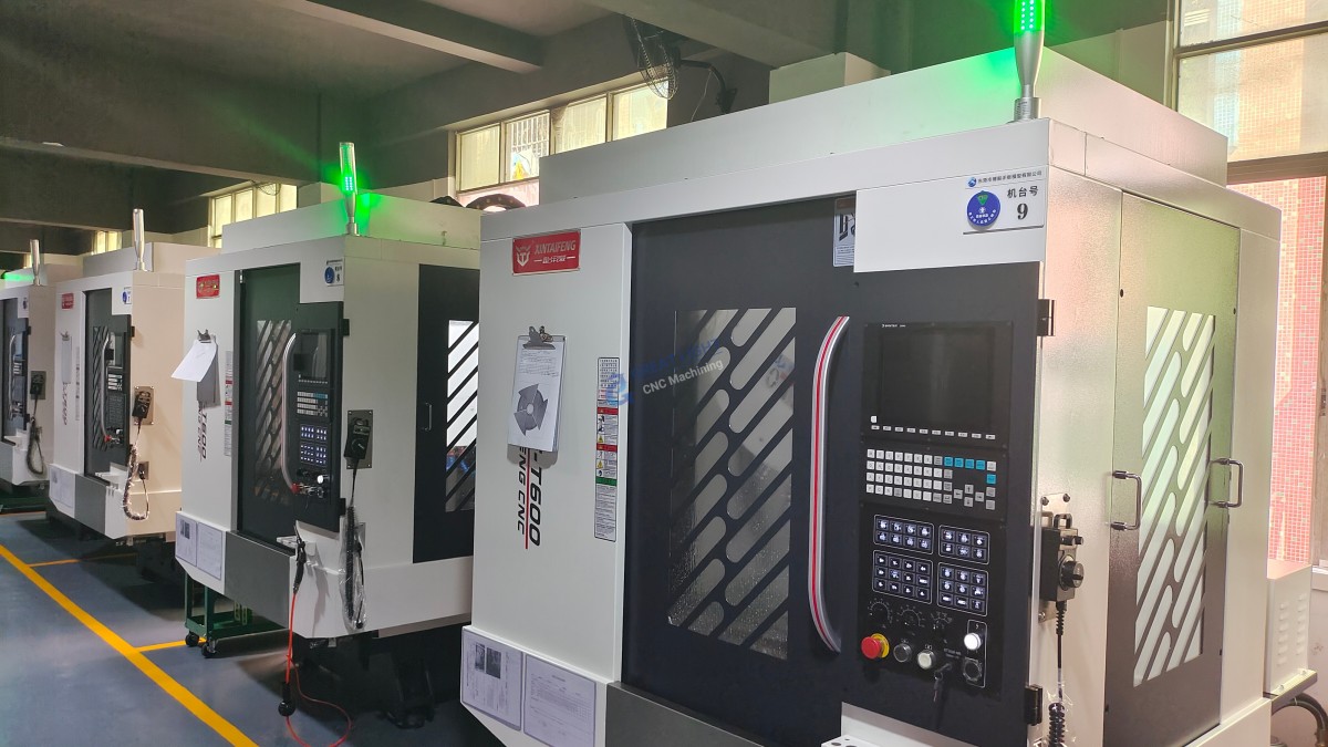
Machine Anatomy: Familiarize yourself with the key components: the controller (often running software like Mach3, UCCNC, or proprietary systems), the spindle (the motor that rotates the cutting tool), the gantry system (which moves the spindle in the X, Y, and Z axes), the workpiece bed (with clamping systems like T-slots, vacuum tables, or screw fixtures), and the dust collection system, which is critical for safety and visibility in woodworking.
Types of Machines: Common configurations include 3-axis (most common for carving), 4-axis (allows rotation for cylindrical carving), and even 5-axis machines for undercutting and complex 3D forms, similar in kinematic principle to the advanced five-axis CNC machining centers we employ for aerospace components.
Tooling: A variety of end mills, ball-nose bits, V-bits (for V-carving lettering), and specialized carving bits are used. Tool material (carbide is standard), flute count, and geometry directly affect finish quality and chip evacuation.
H2: The Professional Workflow: From Design to Finished Carving
H3: Step 1: Digital Design & 3D Modeling
The process begins in the digital realm. Using CAD (Computer-Aided Design) software such as AutoCAD, Fusion 360, or Rhino, you create the precise 2D vector or 3D model of your design. For artistic reliefs, 3D modeling software like ZBrush or dedicated CAM programs with modeling capabilities are used. This stage is analogous to the DFM (Design for Manufacturability) analysis we conduct for complex metal parts, where design intent is translated into a machinable model.
H3: Step 2: CAM Programming & Toolpath Generation
This is the most critical technical phase. The CAD model is imported into CAM (Computer-Aided Manufacturing) software (e.g., Vectric Aspire, ArtCAM, Fusion 360 CAM, or Mastercam).
Material Setup: Define your stock material dimensions (length, width, thickness) and its orientation on the machine bed.
Tool Selection: For each operation, select the appropriate tool from the library, defining its diameter, number of flutes, cutting length, and shank diameter.
Creating Toolpaths: This involves defining how the tool will move to remove material. Common strategies include:
Pocketing: Clearing out areas to a specific depth.
Profiling: Cutting out the final outline of the part.
V-Carving: Using a V-bit to create engraved text or decorative lines with varying widths based on depth.
3D Roughing: A rapid material removal pass with a larger tool, leaving a small amount of stock.
3D Finishing: A final pass with a smaller ball-nose or tapered ball-nose bit to achieve the detailed surface finish. The strategic planning here mirrors the multi-stage roughing, semi-finishing, and finishing processes we use in precision five-axis CNC machining to ensure efficiency and supreme surface integrity.
H3: Step 3: Machine Setup & Workholding
Physical preparation is key to a successful carve.
Material Preparation: Secure your wood blank to the machine bed. A vacuum table is highly efficient for sheet goods. For thicker stock, clamps or screws (placed outside the cutting area) are used. Ensuring the material is flat and securely fastened prevents movement, which is the leading cause of ruined workpieces and broken tools.
Tool Installation: Install the designated tool into the collet of the spindle, ensuring it is tightened to the correct torque specification to prevent slippage.
Setting Zero Points:
X and Y Zero: Typically set to a corner or the center of your material, as defined in your CAM setup.
Z Zero: The most crucial step. Using a touch-off probe or manually with a precision shim, set the Z-zero point on the top surface of your material. An error of a few tenths of a millimeter here can lead to over- or under-cutting.
H3: Step 4: Simulation & Dry Run
Never run a new program directly on your material. Use the CAM software’s simulation function to visually verify the toolpaths, checking for collisions, missed areas, or excessive depth. Following this, perform a dry run with the spindle off and the tool raised slightly above the material to confirm the machine’s physical movements match expectations.
H3: Step 5: Execution & Monitoring
Start the machining process. Begin with a lower feed rate and spindle speed for the initial engagement, then gradually increase to optimal parameters. Constant monitoring is essential:
Listen to the sound of the cut; a high-pitched squeal may indicate a dull tool or too high a feed rate.
Observe chip formation; fine dust may suggest a too-slow feed or dull bit.
Ensure the dust collection system is functioning effectively to keep the work area clear.
H3: Step 6: Post-Processing
Once the machine cycle is complete, carefully remove the part. CNC carving often leaves tool marks or cusp marks, especially on 3D contours. Post-processing may involve:
Sanding: Manual or powered sanding to smooth surfaces.
Hand Detailing: Refining fine details the machine tool couldn’t reach.
Finishing: Applying stains, oils, varnishes, or paints to protect and enhance the wood.
H2: Advanced Considerations for Optimal Results
Grain Direction: Cutting against the grain can cause tear-out. Adjusting toolpath direction (climb vs. conventional milling) and using down-cut end mills can significantly improve edge quality on plywood and laminated woods.
Feeds and Speeds: These are not arbitrary. They are calculated based on the wood species (hardness), tool diameter, number of flutes, and desired finish. Using too-aggressive settings can burn the wood or break tools; too-conservative settings lead to inefficient cuts and poor finish.
Climb vs. Conventional Milling: In climb milling, the tool rotates in the direction of feed, generally providing a cleaner cut in wood but requiring a rigid machine. In conventional milling, the tool rotates against the feed, which can be more forgiving on less rigid setups but may cause more tear-out.
Conclusion
Learning how to use a CNC wood carving machine effectively is a journey that blends artistic vision with engineering discipline. It demands a systematic approach—from flawless digital design and strategic CAM programming to meticulous machine setup and vigilant operation—much like the processes that define high-end metal part manufacturing. While the materials differ, the core philosophy of precision, repeatability, and optimized process control remains constant. For projects where the material is metal and the tolerances are measured in microns, partnering with a specialist like GreatLight CNC Machining Factory ensures that this philosophy is applied with the utmost rigor, leveraging our advanced five-axis capabilities and integrated manufacturing solutions to turn complex designs into reality.
Frequently Asked Questions (FAQ)
Q1: What is the main difference between a CNC wood carving machine and a metal CNC machine?
A: The core differences lie in construction rigidity, spindle power, and cooling. Metal CNCs are built with extremely heavy, rigid frames to withstand high cutting forces, use high-pressure coolant systems, and often have more powerful spindles. Wood CNCs prioritize faster traverse speeds, incorporate effective dust collection, and typically use air-cooled spindles or routers, as cutting forces and heat generation are lower.
Q2: Can I use the same end mills for wood and aluminum on my machine?
A: While possible in a pinch, it’s not recommended. End mills designed for metal often have specific geometries and coatings optimized for chip evacuation and heat dissipation in metal. Wood-cutting end mills may have more aggressive shear angles and are not built to handle the hardness of metals, leading to rapid dulling or breakage. Always use tooling specified for your primary material.
Q3: How do I prevent tear-out and fuzzing when carving wood?
A: Several strategies help: 1) Use sharp tools always. 2) Employ down-cut end mills which push the surface downward. 3) Adjust your feed rate; sometimes a faster feed produces a cleaner cut. 4) Use climb milling where machine rigidity allows. 5) For very problematic woods, consider a light finishing pass with a small step-over.
Q4: My carved details look fuzzy or lack definition. What’s wrong?
A: This is typically caused by a dull cutting tool. As a tool dulls, it burns and tears the wood fibers rather than shearing them cleanly. The solution is to replace the bit. Also, ensure your finishing pass uses an appropriate step-over distance (often 8-10% of the tool diameter for a fine finish).
Q5: Is a vacuum table necessary for wood CNC work?
A: It is one of the most significant upgrades for efficiency and hold-down versatility, especially for sheet goods and intricate carvings where clamps would interfere. It provides even, distributed holding force across the entire underside of the material. For thicker, solid wood blocks, traditional mechanical clamping is often still required.
Q6: For highly complex 3D wood sculptures, what machine capability is most important?
A: For true three-dimensional forms with undercuts and complex contours, a 5-axis CNC machine is essential. It allows the cutting tool to approach the workpiece from virtually any angle, similar to how GreatLight CNC Machining Factory utilizes 5-axis technology for complex aerospace and automotive metal components. This capability unlocks a level of geometric freedom impossible with standard 3-axis machines. To see how this level of advanced manufacturing is applied in an industrial context, you can explore the professional network of leaders in the field on platforms like LinkedIn.



















