How to Build a CNC Plotter Machine: A Practical Guide for Engineers and Makers
The quest to translate digital designs into precise physical drawings or engravings is a cornerstone of prototyping and custom manufacturing. While commercial units are available, constructing your own CNC plotter machine is an immensely rewarding project that demystifies the core principles of computer-controlled motion. For professionals in precision parts machining, understanding this process from the ground up offers invaluable insights into motion control, structural rigidity, and system integration—principles that directly translate to industrial-scale equipment. This guide walks through the process, blending maker-level practicality with an engineer’s perspective on precision and performance.
Understanding the CNC Plotter: Core Principles and Applications
A CNC plotter is fundamentally a 2.5-axis Cartesian robot. It controls a tool (a pen, laser, or engraver) in the X and Y axes to create planar designs, with a Z-axis for tool engagement. The core principles—stepper motor control, gantry stability, and software-to-motion translation—are identical to those in industrial five-axis CNC machining, albeit at a different scale and complexity.
Building one serves multiple purposes:
Educational: Deep, hands-on understanding of G-code, kinematics, and machine calibration.
Prototyping: Rapid iteration on 2D layouts, PCB masks, or decorative engraving patterns.
Customization: Creating a tool tailored for specific materials (paper, vinyl, wood, soft metals) or unique plotting tasks.
Core Components and Sourcing
A functional CNC plotter is built from mechanical, electronic, and software subsystems. Sourcing the right components is the first critical step.
1. Mechanical Frame and Motion System
The frame dictates rigidity, which directly impacts precision and repeatability.
Frame Material: Popular choices include aluminum extrusion profiles (e.g., 20×20 or 20×40 series) for their modularity and strength, or acrylic/MDF sheets for laser-cut designs. For higher performance, machined aluminum plates offer superior stability.
Linear Motion: This defines how the axes move.
Lead Screws: Simple and cost-effective, but can suffer from backlash. Using anti-backlash nuts helps.
Timing Belts and Pulleys: Excellent for high-speed, lightweight plotters, common in CoreXY designs.
Linear Guides/Rails: The professional choice. Paired with linear bearings, they provide smooth, low-friction, and high-rigidity movement. For a plotter mimicking professional-grade motion, precision ground linear rails are ideal.
Gantry Design: The moving bridge (Y-axis) that carries the tool. Its design must minimize deflection. A dual-driven gantry (two motors synchronously driving either side) is superior to a single-drive design.
2. Drive and Control Electronics
This is the “nervous system” of the plotter.
Stepper Motors: NEMA 17 motors are standard for small plotters. Torque rating (e.g., 40Ncm-60Ncm) should be matched to the moving mass.
Stepper Drivers: DRV8825 or TMC2209 drivers control motor current and enable microstepping for smoother motion. TMC2209 drivers are highly recommended for their silent operation and advanced features like stealthChop2.
Controller Board: The brain that interprets commands and controls the drivers. An Arduino UNO paired with a CNC Shield is the most accessible entry point. For more advanced features, a 32-bit board like a Raspberry Pi running specialized CNC software (like LinuxCNC) offers greater power.
Power Supply: A stable 12V or 24V DC power supply rated with sufficient current (e.g., 5-10A) for all motors and electronics.
3. Tooling and End-Effector
The tool defines the plotter’s function.
Pen Holder: A simple servo-controlled solenoid to lift and lower a pen.
Laser Module: A low-power diode laser (e.g., 500mW-5W) for engraving wood, acrylic, or leather. Laser safety is paramount—always use appropriate enclosures and safety glasses.
Spindle/Dremel: A rotary tool for light engraving or milling soft materials. This significantly increases structural demands.
Step-by-Step Assembly and Integration
H2: Phase 1: Mechanical Fabrication and Assembly
Frame Construction: Assemble the base frame ensuring it is square and level. If using extrusion, T-nuts and brackets make this straightforward.
Axis Assembly: Mount the linear rails or smooth rods and bearings. Assemble the X-axis (typically the bed or moving gantry) and Y-axis (the moving carriage). Preload adjustments on linear bearings are crucial to eliminate play.
Drive System Installation: Mount stepper motors and connect them to the lead screws or timing pulleys. Ensure couplings are secure and aligned to prevent binding.
Gantry and Tool Mount: Secure the cross-gantry and attach the Z-axis assembly (tool holder). Ensure the tool mounting point is perpendicular to the working plane.
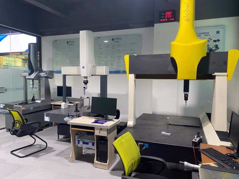
This phase highlights the importance of precision in CNC milling services. At GreatLight CNC Machining Factory, components like custom motor mounts, precision coupling adapters, or rigid aluminum tool plates are routinely manufactured to ensure sub-system accuracy in much larger machines.

H2: Phase 2: Electrical Wiring and Configuration
Wiring: Connect the stepper motors to the drivers on the CNC shield. Connect the drivers to the controller board. Wire the power supply, ensuring correct polarity.
Firmware Installation: Upload firmware to the controller. GRBL is the ubiquitous, powerful firmware for Arduino-based systems. Configuration involves setting steps per millimeter for each axis (calculated from motor steps, microstepping, and lead screw pitch or belt pulley teeth), maximum feed rates, and acceleration.
Testing: Use a sender software (like Universal G-code Sender or ChiliPeppr) to jog each axis manually. Verify movement direction and check for any stalling or unusual noises.
H2: Phase 3: Software Workflow and Calibration
Design to G-Code: Create or obtain a 2D vector design in software like Inkscape, AutoCAD, or Fusion 360. Use a CAM plugin or standalone software (like LaserGRBL for lasers) to generate G-code, defining toolpaths, speeds, and Z-axis movements.
Machine Calibration: This is the most critical step for precision.
Steps-per-mm Calibration: Command the machine to move 100mm, measure the actual distance traveled, and adjust the steps/mm setting in GRBL proportionally.
Squareness Calibration: Plot a perfect square and measure its diagonals. They must be equal. Adjustments may involve mechanical tweaks to the gantry.
Homing/Limiting: Install limit switches at the ends of each axis travel to define a reliable home position and prevent crashes.
Conclusion: From DIY Plotter to Industrial-Grade Precision
Building a CNC plotter machine is a profound exercise in mechatronics. It teaches the intricate dance between mechanical design, electronic control, and software—a dance that scales directly to the world of professional precision CNC machining services.
While a DIY plotter excels at paper, light engraving, and education, it naturally encounters limitations in rigidity, speed, and material compatibility. When your project demands machining aerospace-grade aluminum, creating intricate injection molding prototypes with ±0.001mm tolerances, or producing high-volume custom metal parts with perfect surface finishes, the principles remain the same, but the execution requires industrial-grade resources.

This is where partnering with a specialist like GreatLight CNC Machining Factory becomes strategic. We apply these same fundamental principles—optimized frame rigidity (in our massive machine beds), exquisite motion control (with high-end servo systems and five-axis CNC machining centers), and meticulous calibration—to solve complex manufacturing challenges. Whether you need a single complex prototype or a production run of thousands, our integrated approach from 3D printing to five-axis CNC machining and finishing ensures your vision is realized with uncompromising quality and reliability. The journey from building a plotter to specifying parts for a humanoid robot or next-gen automotive component is a continuum of precision engineering.
Frequently Asked Questions (FAQ)
Q1: What is the typical positioning accuracy I can expect from a DIY CNC plotter?
With careful construction using belts or lead screws and proper calibration, a well-built DIY plotter can achieve repeatable accuracy in the range of ±0.1mm to ±0.5mm. This is suitable for many art and prototyping applications. Achieving tolerances tighter than 0.1mm consistently requires commercial-grade linear guides, ball screws, and a highly rigid frame—essentially moving into the realm of professional machine tools.
Q2: Can I upgrade my DIY plotter to mill or engrave metals like aluminum?
Light engraving on aluminum is possible with a robust frame and a high-speed spindle. However, milling aluminum to precise dimensions is exceptionally challenging on most DIY plotters. It requires immense rigidity to handle cutting forces, a flood or mist coolant system to manage heat and chips, and a spindle with sufficient power and torque. For reliable metal parts, professional CNC milling services with purpose-built machines are recommended.

Q3: My plotter has “wobble” in lines or circles aren’t round. What’s wrong?
This is typically a symptom of backlash or frame flex.
Backlash: Check for loose couplings between motors and lead screws, or slack in timing belts. For lead screws, install an anti-backlash nut.
Frame Flex: Ensure all frame joints are tight. The gantry is often the weakest point; consider reinforcing it or reducing its mass. This issue underscores why industrial machines use massively rigid cast iron or welded steel structures.
Q4: What’s the difference between the GRBL firmware I use and the controllers in industrial CNCs?
GRBL is a brilliant, streamlined firmware for 8-bit microcontrollers. Industrial CNC controllers use vastly more powerful 32-bit or 64-bit processors running real-time operating systems (like LinuxCNC) or proprietary software. They handle complex look-ahead algorithms for smoother high-speed motion, advanced error compensation, networking, and direct integration with sophisticated CAD/CAM suites, managing the complexities of 5-axis CNC machining.
Q5: I’ve designed a custom part for my plotter that needs to be strong and precise. What’s the best way to get it made?
For one-off or low-volume precision parts, CNC machining is ideal. Materials like aluminum 6061 or 7075 offer an excellent strength-to-weight ratio. For complex geometries, 3D printing in nylon (SLS) or resin (SLA) can be a quick solution, though with less strength. Companies like GreatLight Metal specialize in precisely this: rapidly delivering customized precision machining of components from your 3D files, combining services like five-axis CNC machining for complexity with finishing services for a ready-to-use part, effectively becoming an extension of your R&D workshop. For insights into industry applications and partnerships, you can explore professional networks like their presence on LinkedIn.


