
How Do You Program A CNC Machine?
For engineers, designers, and procurement specialists seeking custom precision parts, understanding how to program a CNC machine is not just technical trivia—it’s the key to unlocking manufacturing feasibility, optimizing costs, and ensuring the highest quality. At its core, CNC (Computer Numerical Control) programming is the process of translating a digital part design into a set of precise, step-by-step instructions that guide a machine tool to cut, drill, and shape raw material into a finished component. This intricate language bridges your vision and physical reality.
The Essence of CNC Programming: From CAD Model to Machined Part
Before delving into the “how,” it’s crucial to grasp the “why.” CNC programming defines every aspect of the machining process: tool paths, spindle speeds, feed rates, coolant flow, and more. A well-crafted program ensures dimensional accuracy, superior surface finish, efficient material removal, and extended tool life. Conversely, a poor program can lead to scrapped parts, damaged tools, and machine crashes.
The journey of programming a CNC machine typically follows this high-level flow:
Part Design (CAD): The process begins with a 3D Computer-Aided Design (CAD) model created in software like SolidWorks, CATIA, or Autodesk Inventor. This is the digital blueprint.
Programming & Path Planning (CAM): The CAD file is imported into Computer-Aided Manufacturing (CAM) software. Here, the programmer defines the manufacturing strategy.
Code Generation (G-Code): The CAM software post-processes the strategy into G-code, a low-level programming language the CNC controller understands.
Machine Setup & Execution: The G-code is loaded onto the CNC machine. The machinist sets up the workpiece, tools, and fixtures, then runs the program.
The Two Primary Avenues: Manual Programming vs. CAM Programming
Understanding how to program a CNC machine involves recognizing two distinct methodologies, each with its place in modern workshops.
H3: 1. Manual Programming (G-Code/M-Code)
This is the foundational method, where programmers write code line-by-line using standard G-codes (geometric functions) and M-codes (machine functions).
How it Works: The programmer manually calculates coordinates, feed rates, and tool paths based on engineering drawings. A simple program to drill a hole might look like this:
N10 G90 G54 (Set absolute positioning, use work coordinate system)
N20 M06 T01 (Tool change to tool #1 – a drill)
N30 S1200 M03 (Spindle speed 1200 RPM, clockwise)
N40 G00 X50 Y50 (Rapid move to hole position)
N50 G43 Z10 H01 (Apply tool length compensation, move to safe height)
N60 G01 Z-5 F100 (Drill down 5mm at a feed rate of 100 mm/min)
N70 G00 Z50 (Rapid retract)
N80 M30 (Program end)
Best For: Simple, repetitive operations (like drilling hole patterns), quick edits on the shop floor, or educational purposes to understand machine fundamentals.
Limitations: Extremely time-consuming and prone to human error for complex, multi-axis geometries. It is impractical for the sophisticated 3D contours common in today’s precision parts machining.
H3: 2. CAM (Computer-Aided Manufacturing) Programming
This is the industry standard for precision CNC machining, especially for complex parts. CAM software automates the translation of 3D CAD geometry into efficient tool paths.
How it Works: The programmer works within a CAM software environment (e.g., Mastercam, Siemens NX, HyperMill, Fusion 360). They select the 3D model, choose machining strategies (e.g., roughing, finishing, contouring), define tools from a digital library, and set cutting parameters. The software then visually simulates the entire machining process to detect collisions and optimize the path before generating the final G-code.
Key Advantages:
Handles Complexity: Effortlessly manages 3+ axis simultaneous machining, which is essential for 5-axis CNC machining services of intricate aerospace or medical components.
Efficiency & Optimization: Uses advanced algorithms to calculate the most efficient tool paths, reducing cycle time and tool wear.
Simulation & Safety: Full machine simulation prevents costly crashes by verifying tool clearances and fixture collisions.
Knowledge Capture: Standardizes processes and allows strategies to be saved and reused.
A Step-by-Step Look at the Modern CAM Programming Workflow
To truly understand how to program a CNC machine in a professional context, let’s walk through a typical CAM workflow:
Geometry Import and Preparation: The 3D CAD model (often as a STEP or IGES file) is imported. The programmer may create supplemental geometry, like stock boundaries or containment areas.
Job Setup: Defining the raw material (stock) size and orientation on the virtual machine.
Tool Selection & Management: Selecting appropriate cutting tools from a digital library, specifying their diameter, length, flute count, and material.
Operation Creation: This is the core. The programmer creates a sequence of operations:
Roughing: Uses a larger tool to quickly remove the bulk of material.
Semi-Finishing: Prepares the part for the final finish by leaving a small, consistent amount of stock.
Finishing: Uses precise tools and strategies to achieve the final dimensions and surface finish. This includes strategies for vertical walls, flat faces, and complex free-form surfaces.
Drilling/Tapping/Boring: For creating holes with specific tolerances and thread patterns.
Parameter Definition: For each operation, critical parameters are set:
Spindle Speed (RPM): How fast the cutting tool rotates.
Cutting Feed Rate (IPM/MMPM): How fast the tool moves through the material.
Stepover/Stepdown: The radial and axial depth of each cut, crucial for finish and tool load.
Coolant Strategy: Defining where and how coolant is applied.
Toolpath Simulation & Verification: The software runs a dynamic simulation, showing material removal in real-time. This is checked for gouges, collisions, and inefficient motions.
Post-Processing: The verified toolpath data is run through a “post-processor”—a translator specific to the brand and model of the CNC machine (e.g., a DMG Mori 5-axis post). This generates the final machine-specific G-code file.
Code Transfer & Setup Sheet: The G-code is transferred to the machine (via network or USB). A setup sheet with tool lists, fixture diagrams, and critical dimensions is provided to the machinist.
Beyond Code: The Critical Role of the Programmer/Machinist
The machine is only as capable as the person guiding it. A skilled CNC programmer at a top-tier manufacturer like GreatLight Metal brings indispensable expertise:
Material Science Knowledge: Understanding how aluminum, titanium, Inconel, or PEEK behaves under cutting forces.
Tooling Expertise: Selecting the optimal tool geometry, coating, and holder for each operation.
Design for Manufacturability (DFM): Providing feedback to clients on how to tweak designs for easier, faster, and more cost-effective machining without compromising function.
Process Optimization: Balancing speed, precision, and tool life to find the most economical and reliable production process.
Conclusion: Partnering with Expertise Overwhelms Programming Complexity
So, how do you program a CNC machine? It is a sophisticated synergy of advanced software, profound practical knowledge, and rigorous process control. While the fundamentals of G-code remain, the real-world application for precision parts machining and customization has evolved into a highly specialized engineering discipline.
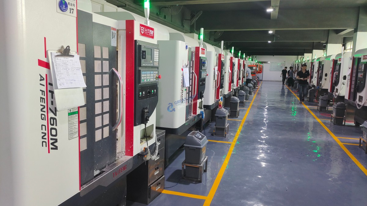
For most businesses, the goal isn’t to master programming internally but to partner with a manufacturer whose programming expertise is a core competitive advantage. This is where a partner like GreatLight Metal proves invaluable. Our engineers don’t just write code; they engineer manufacturing solutions. With a comprehensive equipment fleet (including advanced 5-axis systems), industry-leading CAM software, and a deep commitment to quality enshrined in certifications like ISO 9001:2015 and IATF 16949, we handle the entire programming and machining complexity. We transform your CAD models into flawlessly executed precision components, ensuring you receive parts that meet the most stringent specifications without needing to navigate the intricacies of how to program a CNC machine yourself. By choosing a partner with deep technical expertise, authoritativeness, and trustworthiness (E-A-T), you free your team to focus on design and innovation, confident that the manufacturing execution is in expert hands.
FAQ: CNC Machine Programming
Q1: What is the most common CNC programming language?
A1: G-code (RS-274) is the universal, fundamental language understood by all CNC machines. It consists of alphanumeric codes that command movements (G01 for linear move, G02/G03 for arcs) and machine functions (M03 for spindle start). Modern CAM software generates this code automatically.
Q2: Can I machine a part directly from a CAD file without CAM programming?
A2: No. A CAD file (e.g., .SLDPRT, .STEP) is a geometric model. It contains no information about how to make the part—tool selection, cutting order, speeds, or feeds. CAM software is the essential intermediary that translates geometry into actionable manufacturing instructions (G-code).
Q3: What software is best for CNC programming?
A3: There is no single “best” software, as it depends on part complexity and industry. For high-end, complex 5-axis CNC machining, powerful suites like Siemens NX, HyperMill, or Mastercam are industry standards. For simpler parts or prototyping, Fusion 360 offers integrated CAD/CAM at a lower cost. Professional manufacturers like GreatLight typically invest in and master multiple platforms to handle diverse client needs.
Q4: How long does it take to program a CNC part?
A4: Programming time varies dramatically. A simple 2D bracket might be programmed in under an hour. A complex, tight-tolerance aerospace component with 3D surfaces requiring multi-axis simultaneous machining could take several days of programming, simulation, and optimization. This upfront engineering time is crucial for ensuring error-free, efficient production.
Q5: How do manufacturers ensure the CNC program is error-free before cutting metal?
A5: Rigorous verification is multi-layered:
CAM Software Simulation: A virtual machine simulates the entire job, highlighting collisions and inefficiencies.
Dry Runs: The machine runs the program without the workpiece or with a safe offset to verify movements.
First-Article Inspection: The first part off the machine is meticulously measured using CMMs and other metrology tools to validate it against the original CAD model before full production runs.
Q6: Why should I choose a manufacturer with strong in-house programming capability?
A6: In-house programming expertise directly translates to better parts, faster turnaround, and lower costs. It enables seamless DFM feedback, rapid iteration on prototypes, and optimized production processes. A manufacturer relying on outsourced or basic programming cannot offer the same level of integration, control, or problem-solving agility. It is a cornerstone of true manufacturing partnership, as demonstrated by leaders in the field on platforms like LinkedIn.



















